Common Mode Noise Filter
- Summary
- Abstract
- Description
- Claims
- Application Information
AI Technical Summary
Benefits of technology
Problems solved by technology
Method used
Image

Examples
exemplary embodiment 1
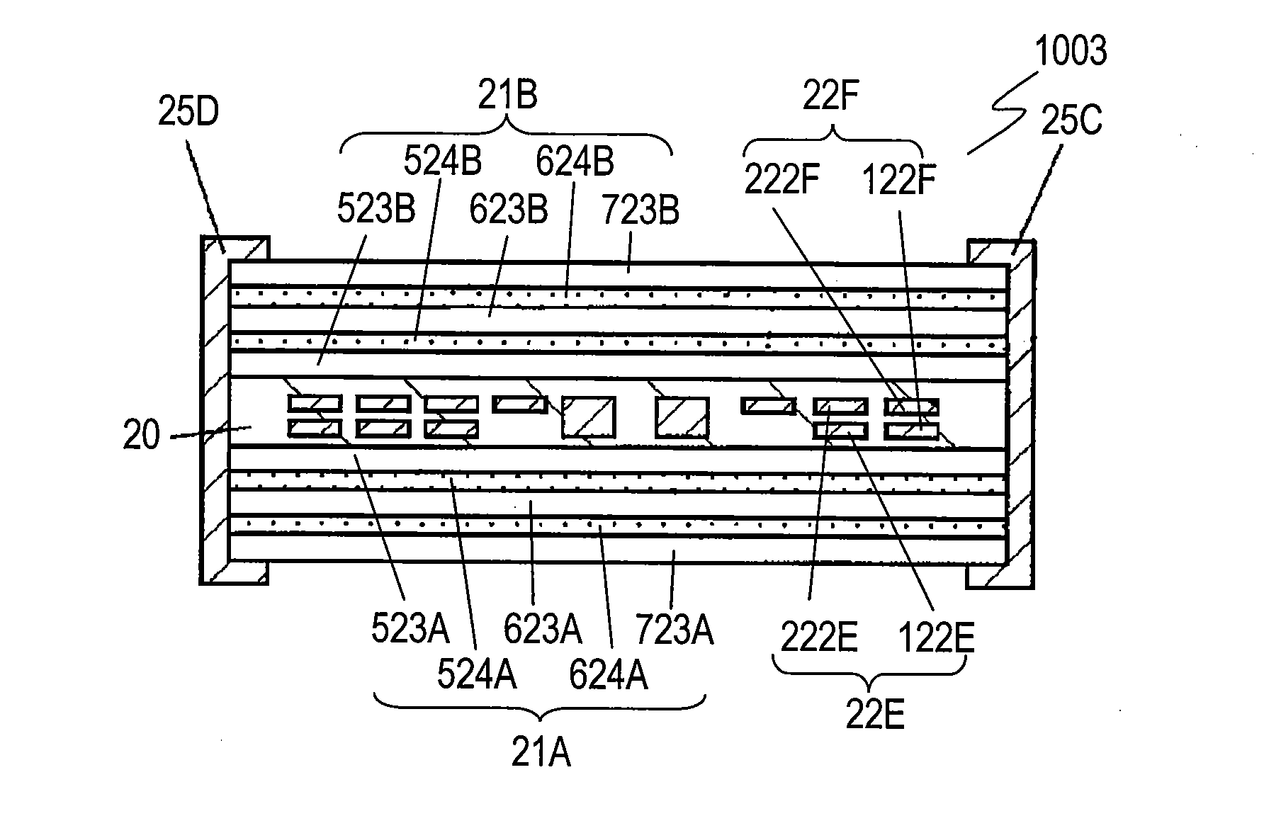
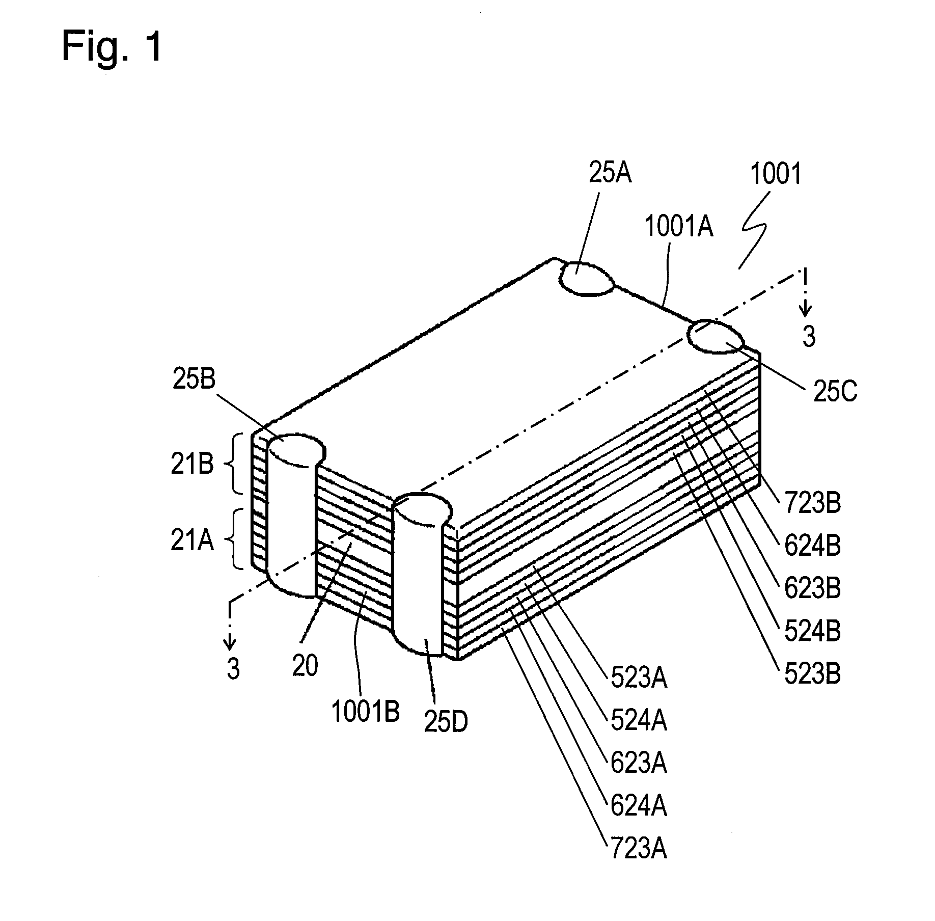
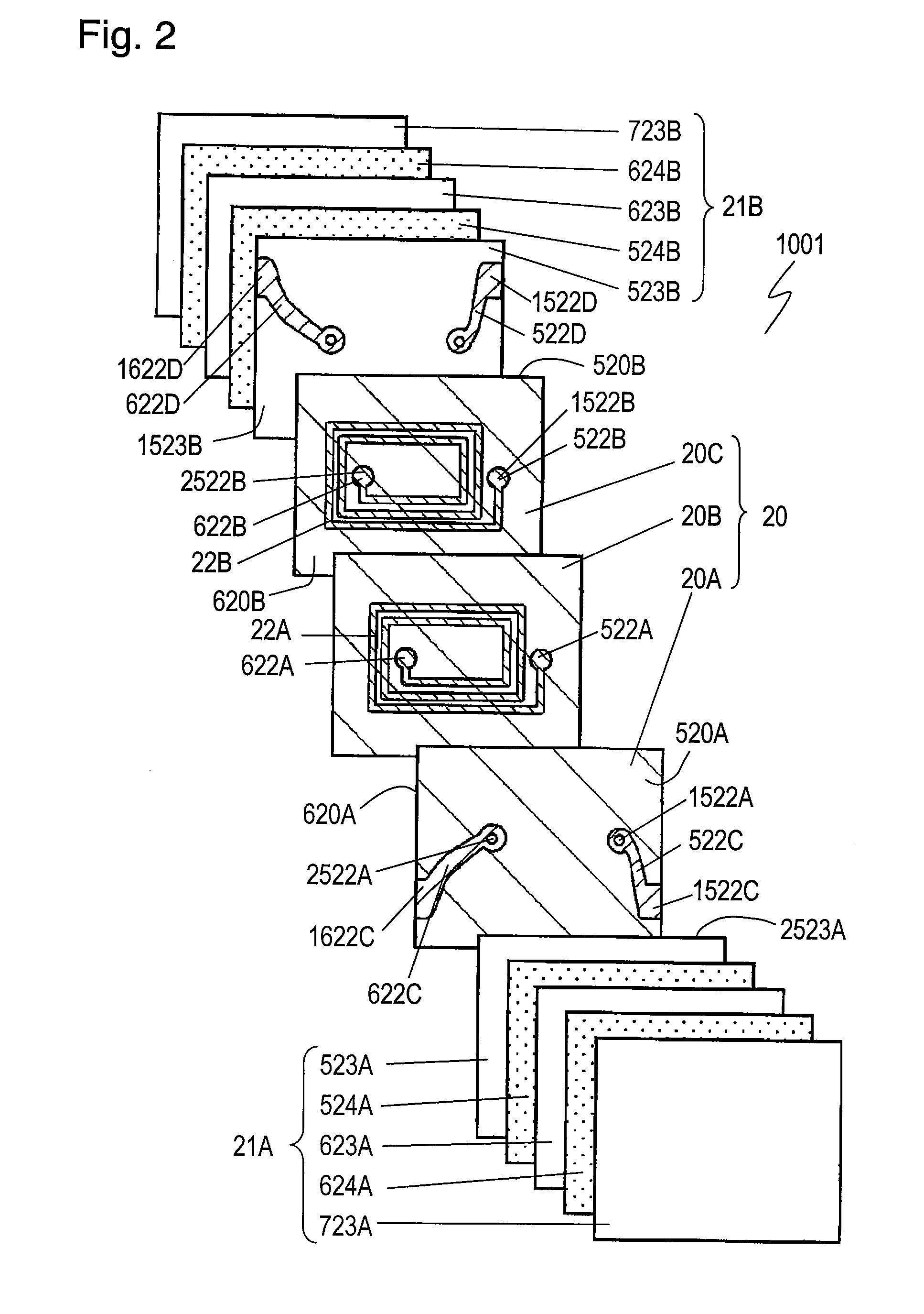
[0040]FIG. 1 is a perspective view of common mode noise filter 1001 according to Exemplary Embodiment 1 of the present invention. FIG. 2 is an exploded view of filter 1001. FIG. 3 is a sectional view of filter 1001 at line 3-3 shown in FIG. 1.
[0041]Common mode noise filter 1001 includes nonmagnetic layer 20, magnetic layers 21A and 21B, plane coils 22A and 22B, and external electrodes 25A to 25D. Nonmagnetic layer 20 is made of nonmagnetic insulating material, such as glass ceramic, and has surface 520A and surface 520B opposite to surface 520A. Magnetic layer 21A is provided on surface 520A of nonmagnetic layer 20. Magnetic layer 21B is provided on surface 520B. Plane coils 22A and 22B are provided between magnetic layers 21A and 21B and contact nonmagnetic layer 20. Coils 22A and 22B face each other. In filter 1001, plane coils 22A and 22B are embedded in nonmagnetic layer 20. Plane coil 22A has ends 522A and 622A. Ends 522A and 622A are connected to external electrodes 25A and 25...
exemplary embodiment 2
[0066]A common mode noise filter according to Exemplary Embodiment 2 has the same structure as common mode noise filter 1001 shown in FIGS. 1 and 2. Nonmagnetic layer 20 of the common mode noise filter according to Embodiment 2 contains glass component.
[0067]Ceramic green sheet with thicknesses of about 50 μm to be nonmagnetic segment layers 20A to 20C of nonmagnetic layer 20 were produced from non-borosilicate glass (SiO2—CaO—ZnO—MgO based glass) powder containing crystal as filler that can be fired at a temperature not higher than 920° C. and has a linear expansion coefficient of about 100×10−7 / ° C. Fifty samples according to Embodiment 2 each including nonmagnetic layer 20 were produced by stacking nonmagnetic segment layers 20A to 20C. FIG. 11 shows the bonding strength of external electrodes 25A to 25D of these samples which were measured by the same method as filter 1001 according to Embodiment 1.
[0068]As shown in FIG. 11, nonmagnetic layer 20 containing the glass material pro...
exemplary embodiment 3
[0071]FIG. 8 is a perspective view of common mode noise filter 3001 according to Exemplary Embodiment 3 of the present invention. FIG. 9 is a sectional view of filter 3001 at line 9-9 shown in FIG. 8. Component identical to those of the common mode noise filter according to Embodiments 1 and 2 shown in FIG. 1 are denoted by the same reference numerals, and their description is omitted.
[0072]Common mode noise filter 3001 includes magnetic layers 1021A and 1021B instead of magnetic layers 21A and 21B of common mode noise filter 1001 according to Embodiment 1. Magnetic layer 1021A further includes insulator layer 724A containing glass component provided on magnetic oxide layer 723A of magnetic layer 21A of filter 1001. Magnetic layer 1021B further includes insulator layer 724B containing glass component provided on magnetic oxide layer 723B of magnetic layer 21B of filter 1001. That is, the respective outermost layers of magnetic layers 1021A and 1021B are insulator layers 724A are 724...
PUM
 Abstract
Description
Claims
Application Information
 - Generate Ideas
- Intellectual Property
- Life Sciences
- Materials
- Tech Scout
- Unparalleled Data Quality
- Higher Quality Content
- 60% Fewer Hallucinations
Browse by: Latest US Patents, China's latest patents, Technical Efficacy Thesaurus, Application Domain, Technology Topic, Popular Technical Reports.
© 2025 PatSnap. All rights reserved.Legal|Privacy policy|Modern Slavery Act Transparency Statement|Sitemap|About US| Contact US: help@patsnap.com