
Coupling Composition for Optical Fiber Cables

Inactive Publication Date: 2009-01-01
DRAKA COMTEQ BV
View PDF21 Cites 89 Cited by
  • Summary
  • Abstract
  • Description
  • Claims
  • Application Information

AI Technical Summary

Benefits of technology

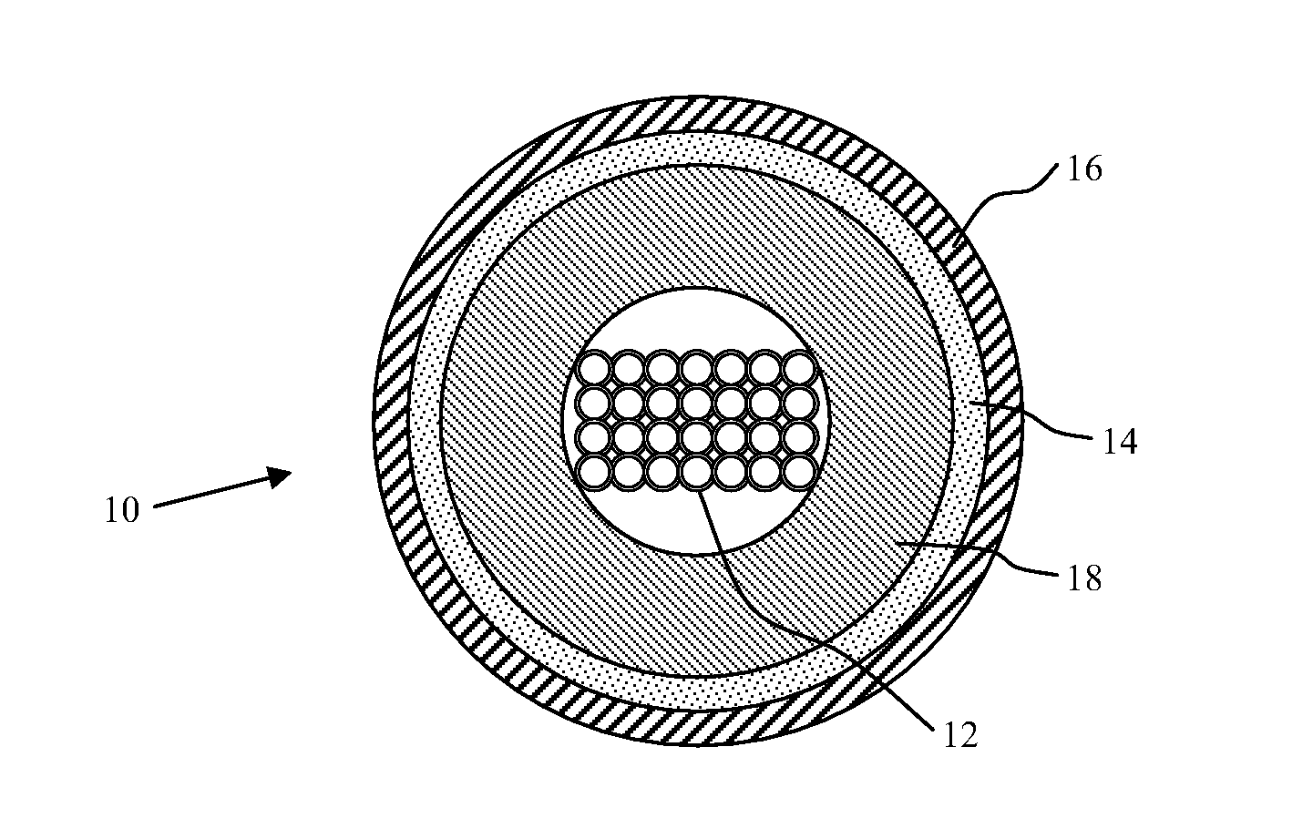
[0012]In another aspect, the invention embraces optical fiber cables that use the cohesive gel coupling composition. For instance, the coupling composition may fully or partially fill the free space surrounding the optical fibers within the buffer tube. Coupling provided by elements formed from the present coupling composition is superior to that provided by conventional water-swellable tapes.

Problems solved by technology

First, forces may develop on the optical fibers due to contact with rough, hard, or uneven surfaces within the optical fiber cables.
Such contact, for example, may result from thermal cable expansion or contraction, which can cause microbending and macrobending effects.
This, in turn, can lead to signal attenuation or signal loss.
Not only can these effects hamper accessibility to the fibers during connection operations (e.g., splicing), but also insufficient coupling can lead to excess and / or unevenly distributed optical fiber length (e.g., optical fibers accumulating in a confined space).
Such accumulation may cause bending or otherwise force contact between the optical fibers and other cable elements, which can likewise lead to microbending and macrobending.
If water intruding into the cables can spread (e.g., flow) along the length of the cables to these electronic devices, severe damage to the electronic systems may result.
The addition of these layers, however, can lead to larger cables, which are not only more costly to produce and store but also heavier, stiffer, and thus more difficult to install.
That usefulness notwithstanding, such thixotropic filling greases are relatively heavy and messy, thereby hindering connection and splicing operations.

Method used


Image

  • Coupling Composition for Optical Fiber Cables
  • Coupling Composition for Optical Fiber Cables
  • Coupling Composition for Optical Fiber Cables

Examples


working example

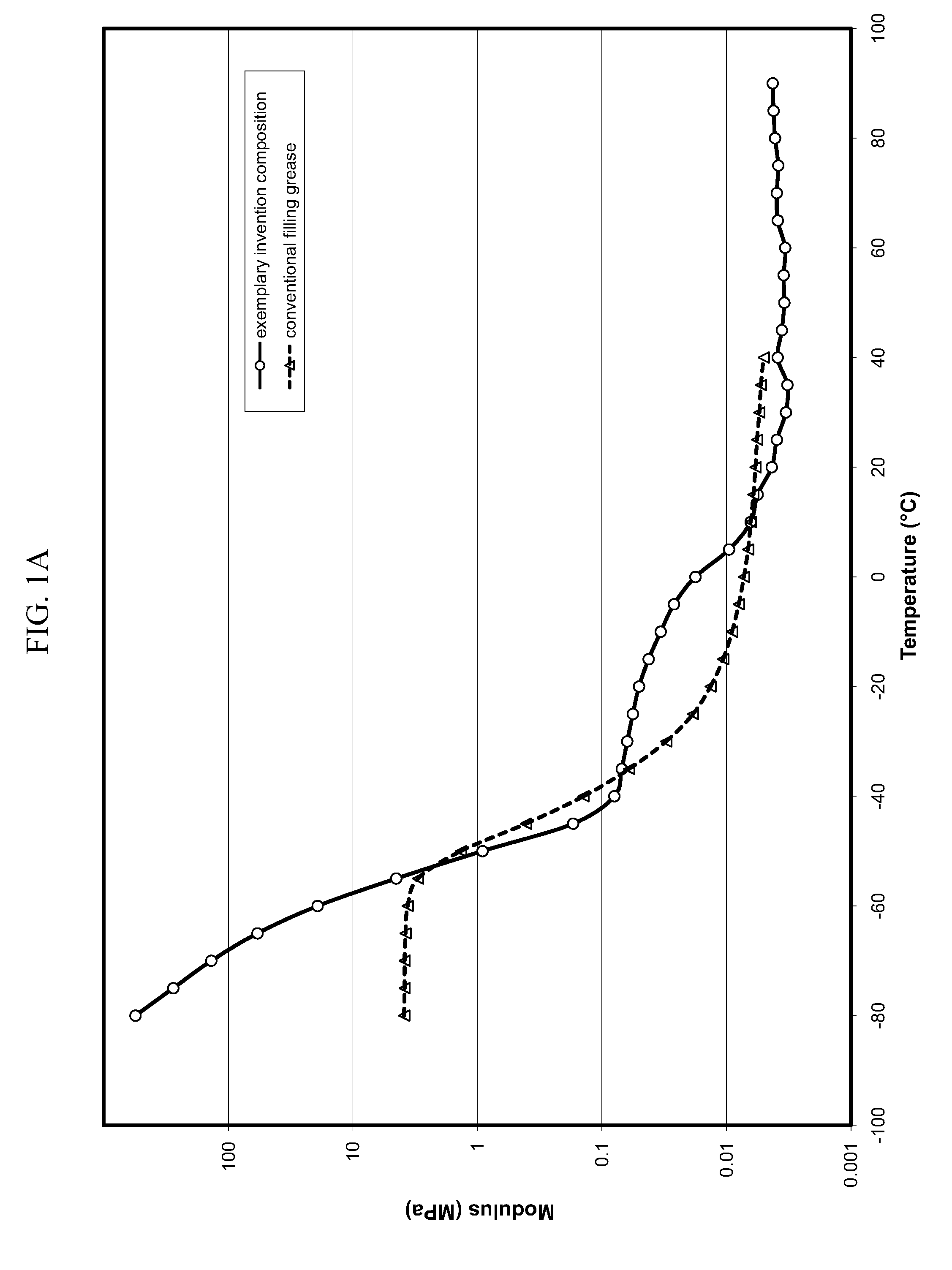
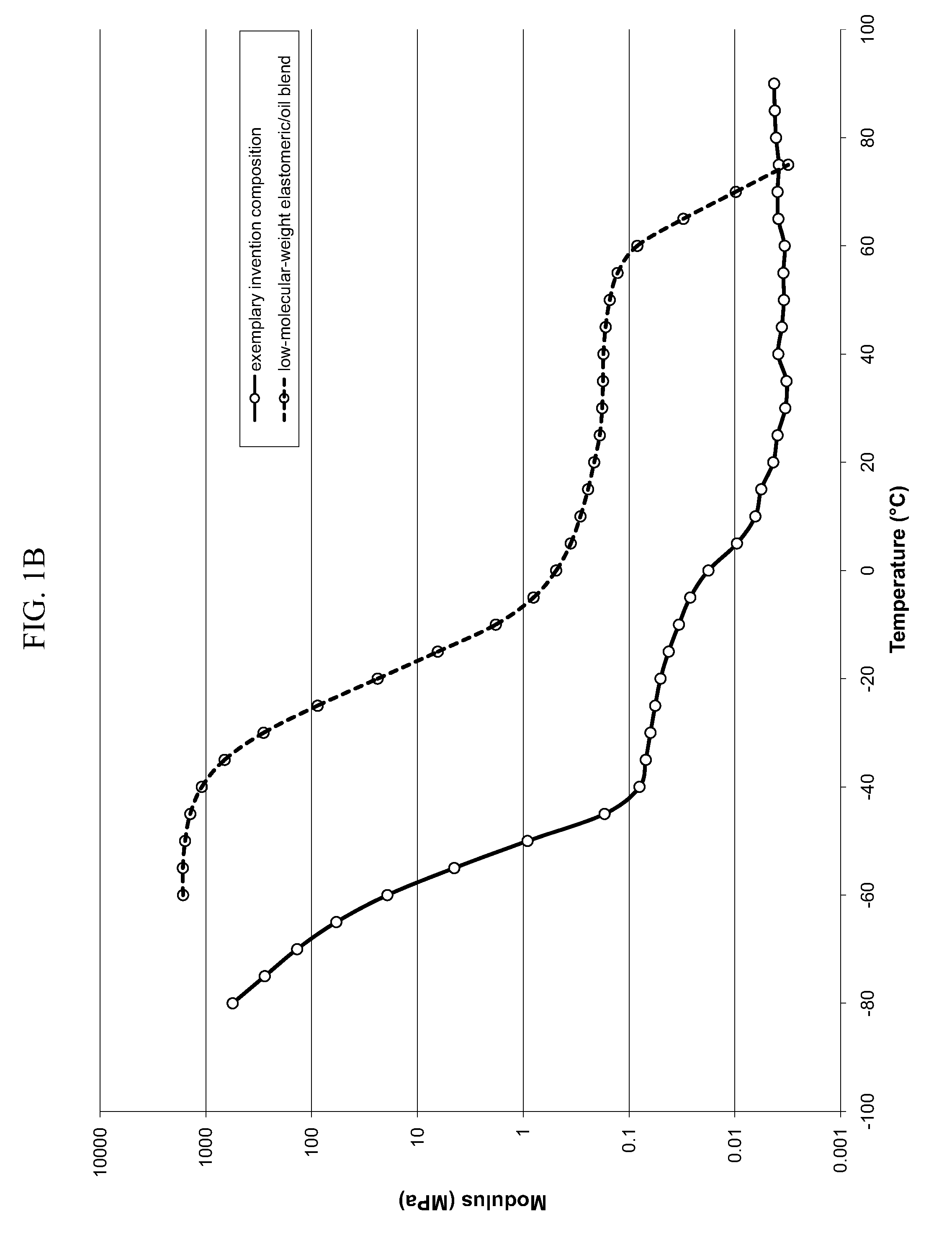
[0068]Styrene-ethylene / butylene-styrene block copolymers possessing a number-average molecular weight of about 200,000 g / mol or higher, commercially available under the trade name KRATON G-1651, were slowly blended into a highly branched isoparrafinic polyalphaolefin oil that was pre-heated to about 290° F. The polymer / oil blend ratio was about 6.5:93.5. The polyalphaolefin oil, commercially available from Chevron Phillips under the trade name SYNFLUID PAO 7, had a viscosity of about 7 centistokes at 100° C. The mixture was blended for 30-60 minutes, and then the resultant coupling composition was poured under pressure into barrels. Thereafter, the coupling composition was melted and pumped through a die and thereby integrated into an optical fiber cable.

[0069]The styrene-ethylene / butylene-styrene block copolymers and the polyalphaolefin oil can be (and perhaps should be) mixed at higher temperatures (e.g., 300-350° F. or more) to facilitate improved blending. This, however, require...


PUM


Abstract

The present invention relates to a novel coupling composition that is used within optical fiber cables to protect optical fibers and to couple the optical fibers and the surrounding buffer tube casing. The present invention also relates to optical fiber cables that use the novel coupling composition.

Description

CROSS-REFERENCE TO PRIORITY APPLICATION[0001]This application hereby claims the benefit of U.S. Provisional Patent Application Ser. No. 60 / 946,754, for Coupling Composition for Optical Fiber Cables (filed Jun. 28, 2007) via 35 U.S.C. § 119. U.S. Provisional Patent Application Ser. No. 60 / 946,754 is hereby incorporated by reference in its entirety.FIELD OF THE INVENTION[0002]The invention relates to coupling compositions that are useful in dry optical fiber cables.BACKGROUND[0003]Optical fiber cables are used to transmit information including telephone signals, television signals, data signals, and Internet communication. To preserve the integrity of the signal transported by optical fiber cables, certain design factors warrant consideration.[0004]First, forces may develop on the optical fibers due to contact with rough, hard, or uneven surfaces within the optical fiber cables. Such contact, for example, may result from thermal cable expansion or contraction, which can cause microben...

Claims


Application Information

Patent Timeline
IPC IPC(8): G02B6/02
CPCG02B6/4411G02B6/4494G02B6/4429G02B6/44384
Inventor PARRIS, DONDECHRISTOPHER, GREGQUINN, JUSTIN ELISHALOOKADOO, BOYCE
Owner DRAKA COMTEQ BV
Learn More