Induction tunnel coil

a technology of induction tunnel coil and coil body, which is applied in the field of electromagnetic induction to heat electrically conductive workpieces, can solve the problems of slow control response of oil's thermal mass, limited application of oil-heated devices, and forming and/or machining customized groove winding templates, etc., and achieves the effect of low cost and fast efficiency

Inactive Publication Date: 2009-01-01
XALOY INCORPORATED
View PDF29 Cites 11 Cited by
  • Summary
  • Abstract
  • Description
  • Claims
  • Application Information

AI Technical Summary

Benefits of technology

[0015]The method provides a unique, low cost, fast efficient way to manufacture an induction coil and to install a thermal insulation layer while optimally setting and constraining the cable winding pitch.

Problems solved by technology

Due to the added cost and complexity, and the slower control response of the oil's thermal mass, oil-heated devices are limited to special applications, such as the processing of thermosets, including phenolics, ureas, and rubber.
However, forming and / or machining customized grooved winding templates to match the unique dimensional requirements of each application, such as groove pitch and the internal and external diameters of the sleeve, is exceedingly time consuming and costly.

Method used


Image

  • Induction tunnel coil
  • Induction tunnel coil
  • Induction tunnel coil

Examples


Embodiment Construction

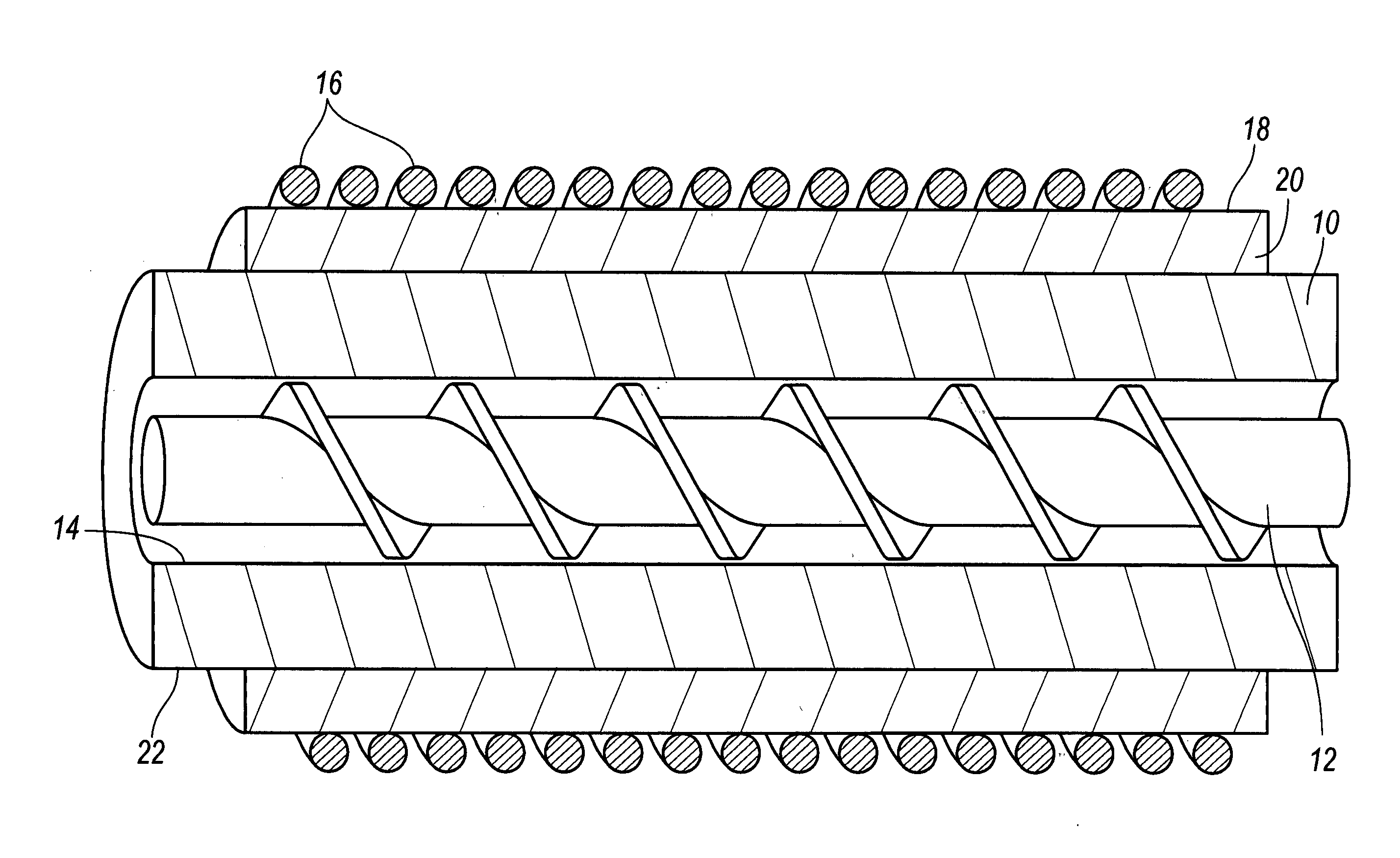
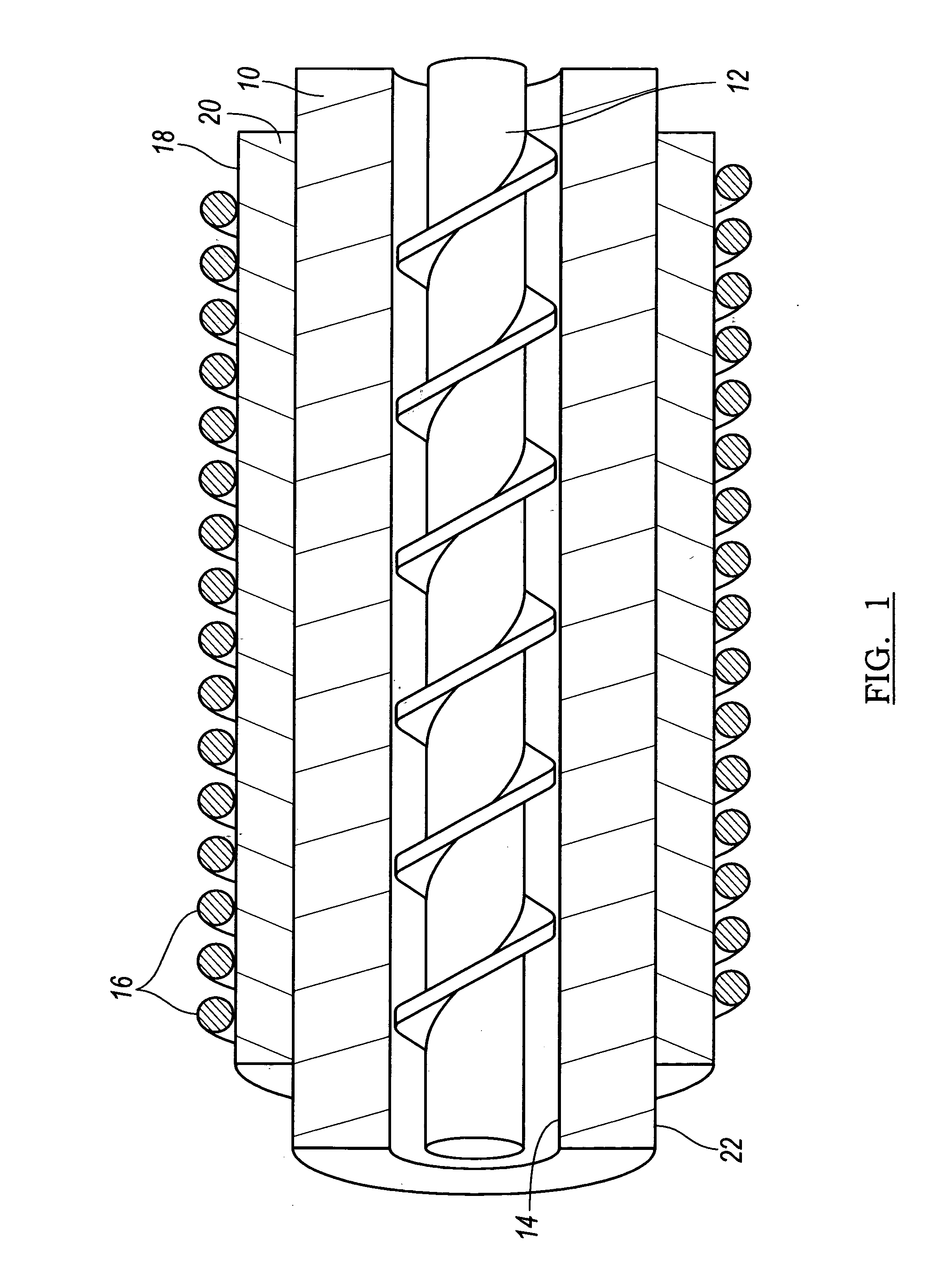
[0034]Referring now to the drawings, there is illustrated in FIG. 1 a longitudinal segment of a cylindrical metal extrusion or molding barrel 10 for use with an extruder or molding machine. The barrel 10 contains processed material fed through a feed port in the barrel, and then the material is mixed, heated, and perhaps melted into a homogeneous molten state. Of course, there are various means of molding and extruding, such as injection molding, blow molding, injection blow molding, extrusion blow molding, sheet extrusion, and profile extrusion, all of which are herein generally referred to as “plastics processing”, and to all of which the present invention may be applied as stated previously.

[0035]When the barrel 10 is used with extruders and molding machines, a screw 12 rotates within a bore 14 formed in the barrel to ingest the processed material and to transport it along a helical path toward an exit where a nozzle or die is located.

[0036]The extrusion or molding barrel 10 is h...


PUM

PropertyMeasurementUnit
frequencyaaaaaaaaaa
thickaaaaaaaaaa
thicknessaaaaaaaaaa

Abstract

A system for supplying processed material includes a barrel for transporting the processed material, having a chamber and an electrically conductive wall enclosing the chamber. The barrel has a length and an outer surface. Thermal insulation extends along at least a portion of the length and around the outer surface and provides an exterior surface whose contour is uniform and formed without grooves. A coil comprising an electric conductor is encased in an electrical insulating sheath. The coil contacts and encircles the exterior surface in loops forming an induction winding that extends along at least a portion of the length and around the exterior surface in a spiral path. An induction power supply is used for supplying alternating current to the coil at a relatively high frequency.

Description

[0001]This application claims priority to and the benefit of U. S. Provisional Application No. 60 / 937,171, filed Jun. 26, 2007, the full disclosure of which is incorporated herein by reference.BACKGROUND OF THE INVENTION[0002]1. Field of the Invention[0003]This invention relates to heating an electrically conductive workpiece by electromagnetic induction. More particularly, the invention relates to induction heating an extrusion or molding barrel using alternating electric current at a high frequency.[0004]2. Description of the Prior Art[0005]It is commonly known how an extruder or molding machine takes fluids or solids, such as plastic or magnesium in such forms as pellets, powder, granules, or chips (hereinafter collectively referred as processed “material”) fed through a feed port in the cylindrical metal tube or barrel, and then mixes, heats, and perhaps melts the processed material into a homogeneous molten state. Of course, there are various means of molding and extruding, suc...

Claims


Application Information

Patent Timeline
Patent Type & Authority Applications(United States)
IPC IPC(8): B28B21/52H05B6/36
CPCB29C47/0021H05B6/36B29C47/82B29C47/003B29B7/38B29B7/726B29B7/823B29B7/826B29C48/08B29C48/12B29C48/83B29C48/832
Inventor TAYLOR, BRUCE F.KADYKOWSKI, ROBERT
Owner XALOY INCORPORATED
Why Eureka
Try Eureka