[0013]In a first aspect of the invention, the
system further includes an alignment indicator
system, such as a
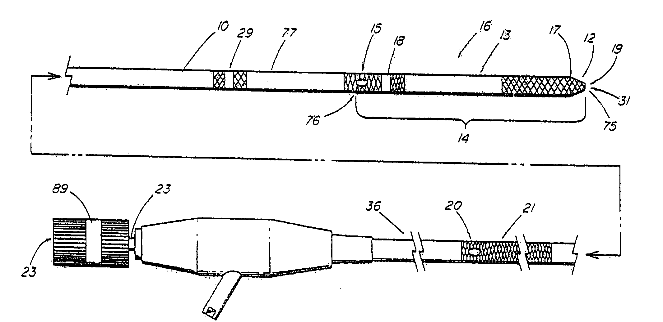
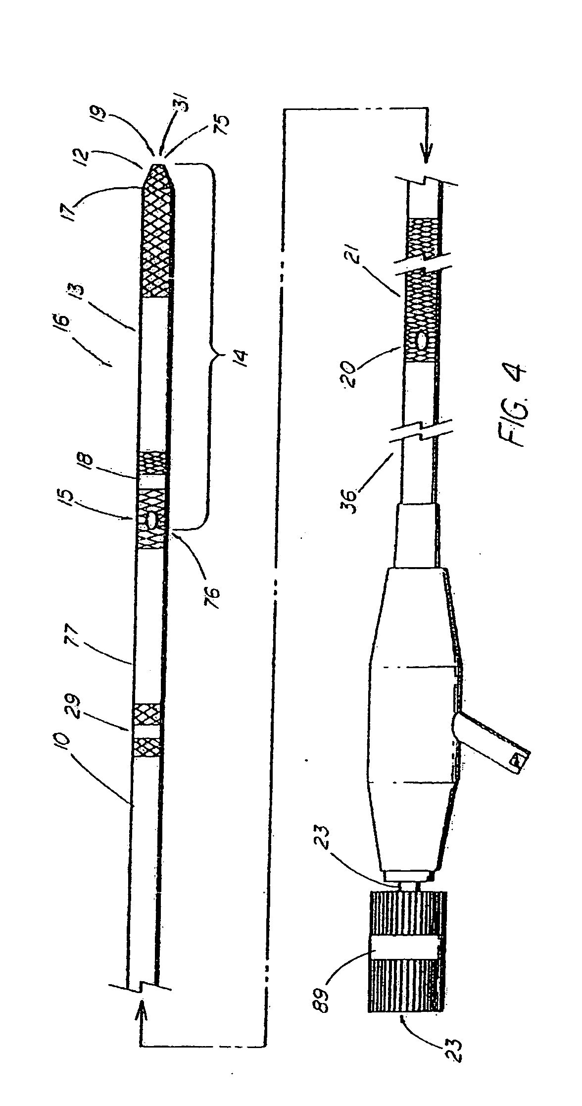
system of indicia (e.g., radiopaque markers, external markings, endoscopic markings, etc.) located about the wire guide and / or first elongate medical device that can be utilized by the operator in locating the position of the distal end or
distal portion of the wire guide relative to the proximal end of the
coupling region, such as at a side
access port or aperture (e.g., scive) through which the wire exits. The alignment indication system advantageously allows the physician to control when the two devices are coupled or uncoupled within the work site and helps provide confirmation that uncoupling has occurred. Without the ability to receive such confirmation, it would be extremely difficult for the physician to attempt, with any confidence, the uncoupling of the
catheter from the wire guide (e.g., under fluoroscopic guidance) without knowing when uncoupling has occurred or is about to occur. Depending on the location or work site within the body and the device being delivered, an attempt to ‘blindly’ uncouple devices can lead to loss of wire guide access, especially if the device is prematurely withdrawn with the wire guide still engaged. Furthermore, the amount of relative movement between the device and the wire guide required to ensure that uncoupling had occurred would generally be much greater than if indicia were utilized, thus increasing risks such as the wire guide being withdrawn too far and access lost or encountering situations where there is insufficient space within the work site left for uncoupling to take place. Typical rapid exchange devices are not configured with the necessary radiographic or other appropriate indicia since the exchange procedure is intended to take place outside of the patient. The external exchange is a slower process and dictates removal of the first
catheter before another catheter or wire guide can be advanced to the work site over an existing * device (which always must be a wire guide or guiding device in traditional rapid exchange).
[0016]A third series of embodiments of the system of indicia include markings that are configured to be viewable by a fiberoptic
endoscope or videoendoscope (e.g., duodenoscope, gastroscope, bronchoscope,
ureteroscope, etc.). In devices configured for accessing the pancreatobiliary system, the indicia comprise a marking located on both the wire guide and elongate medical device disposed within an intermediate portion of each, which is typically located distal to the viewing lens or video
chip of the scope, but proximal to the ampullary orifice during a typical procedure, such that they can be aligned by using the video monitor (or viewing port) to ascertain that uncoupling within the duct has occurred. The device may include other endoscopic indicia useful during the remote uncoupling procedure. For example, a biliary catheter may include a depth marking at a designated distance from the catheter tip (e.g., 10 cm) which when buried within the papilla, indicates that IDE can be performed safely within the duct without risking loss of wire guide access. Furthermore, the
distal portion of the wire guide can be distinctive in appearance (e.g., black) as a visual cue to warn the physician if the tip is in danger of pulling completely out of the duct, which would require recannulation of the papilla. The second and third system of indicia do not require external imaging, thus the physician can advantageously limit the time that the patient is exposed to
fluoroscopy. For example,
fluoroscopy can be used only at selected, critical times during the procedure with at least one of the other types or indicia being used elsewhere for alignment guidance.
[0019]When the physician, using at least one component of the alignment indicator system, has determined that the tip of the wire guide has disengaged from the
coupling region of the primary access device, the first device can be easily removed by merely pulling it back out of the
endoscope accessory channel (or
introducer sheath in the case of vascular or certain other non-endoscopic applications). Removal is greatly facilitated by the
elimination of friction which would have otherwise existed between the wire guide and catheter if the wire resided within the channel or lumen. Although some of the aforementioned MICROVASIVE RX™ biliary devices (e.g., the AUTOTOME™ sphincterotome) include a side port within the
distal portion, all of the devices lack the combination of indicia that make a remote or intraductal exchange clinically practical or even possible. Furthermore, those devices that include an open channel extending proximally of the side
access port cannot be uncoupled within the duct or work site regardless of the lack of indicia since the proximal portion of the wire guide tends to ‘seek’ and reenter the channel when both devices are residing within the accessory channel of the scope. Thus, remote disconnection is rendered impossible without some means to releasably disengage the wire from the channel.
[0022]After gaining access to the passageway by one of the aforementioned routes, the wire guide is guided under external imaging, such as
fluoroscopy, into the desired location. Optionally, if the first device is a sphincterotome or other type of deflectable catheter, the operator can manipulate the shape and orientation of the catheter tip portion to help guide the tip of the second wire guide into the opposite (or side)
branch of the duct or vessel. Orientation within the work site can be facilitated with a rotatable
handle to direct the tip. Furthermore, it has been demonstrated that certain shorter wire guides, such as the illustrative 185 cm biliary wire guide of the present invention, are sufficiently torqueable such that an operator can simply rotate the wire with his or her fingers to achieve similar results in most instances.
[0024]In still another aspect of the invention, the system of devices adapted for remote uncoupling or ultra-short wire techniques includes a delivery catheter for plastic tubular drainage stents and a technique for deployment that allows for placing multiple stents side by side within the
bile duct using a single cannulation procedure. By placing the side
access port on the inner carrying member (over which the
stent is mounted) at a point distal to the
stent, the wire guide can be uncoupled within the duct and the
stent deployed without having to withdraw the entire system, including the wire, in the process. The junction between the inner carrying member and wire guide can be advantageously used to ‘catch’ the stent when the inner member is pulled back, thus allowing the entire
delivery system, including the stent, to be pulled back within the duct. This feature, which is not present in other stent delivery systems, is especially important to address situations when the stent is advanced too far into the duct and needs to be repositioned. After the stent is in the correct position for deployment, the inner carrying member is advanced and / or the wire guide withdrawn to uncouple the two, allowing the inner carrying member to be withdrawn through the stent and from the duct while the wire guide remains behind for a second stent delivery catheter (and additional stents) to be advanced into the duct and placed along side the first stent.
Pigtail stents and others that include shaped distal portions for anchoring can be temporarily straightened during delivery by the wire guide which traverses the
coupling region.

