
Wireless Network System and Devices

a wireless network and wireless technology, applied in the field of wireless network systems and devices, can solve the problems of 16 mbps being available to the application layer, inefficient, and unsatisfactory performance of the 802.11g wireless home media system for consumers, and achieves less sensitivity to the orientation of the device, and improves the resistance to fast fading.

Inactive Publication Date: 2009-01-01
SKY
View PDF2 Cites 45 Cited by
  • Summary
  • Abstract
  • Description
  • Claims
  • Application Information

AI Technical Summary

Benefits of technology

"The present invention provides a wireless network device with orthogonally polarised antennas that provide transmit and / or receive polarisation diversity. This diversity enhances resistance to fast fading and reduces sensitivity to the orientation of the device. The antennas are arranged so that their nulls do not coincide, resulting in a combined antenna pattern that is uniform in coverage in a 3D environment. The antennas may be integrated within or mounted on a housing of the device, which reduces the risk of damage and provides convenient use. The invention also provides a wireless network system comprising a transmitter and a receiver with orthogonally polarised antennas that apply maximal ratio combining for improved gain and resistance to fading. The transmitter may transmit data using polarisation-time block codes, and the wireless network physical layer may be similar to the 802.11a standard. The invention also includes a slot antenna that generates a highly polarised beam and can be conveniently mounted on a conductive surface of a wireless device."

Problems solved by technology

In reality, wireless home media systems based on the 802.11g standard have not provided satisfactory performance for consumers, for a number of reasons.
First, the standard includes a high signaling overhead, and uses a fairly inefficient stop-and-wait medium access control (MAC) method, resulting in only about 16 Mbps being available to the application layer, even in ideal conditions.
Next, the home environment causes significant blocking, if the transmitter and receiver are not in the same room; for example, a wall might incur 10 dB attenuation.
Significant propagation loss is incurred as the distance between the receiver and the transmitter increases.
Furthermore, the user cannot be required to position the media centre in an ideal, central location and at an ideal orientation.
Also, the 2.4 GHz band used by 802.11 b / g is subjected to interference from domestic microwave ovens, and from Bluetooth devices.
The result is that an 802.11g standard network cannot reliably distribute even one high-quality video stream throughout the typical house, because the existing wireless network technology cannot reliably provide a constant required minimum bandwidth.
However, this solution is not suitable for an interactive system, where a user at the receiver wants to change the content of the media stream, for example to change channels or to rewind or fast forward a programme.
The delay caused by buffering causes a corresponding delay in the response to commands from the user, which is not acceptable, particularly when the user wants to ‘surf’ by rapidly changing channels.
This system provides a simple point-to-point wireless link and does not allow multiple devices to receive wireless audio / video steams independently, and there is some loss of quality due to analog conversion prior to retransmission.
Typically, the unencrypted broadcast is only output from the receiver in analog format, so that the content cannot be redistributed without loss of quality (and because most television sets only have analog video inputs).
Hence, at least one of the proposed solutions is incompatible with DRM.

Method used


Image

  • Wireless Network System and Devices
  • Wireless Network System and Devices
  • Wireless Network System and Devices

Examples


Embodiment Construction

Wireless Media Distribution Network

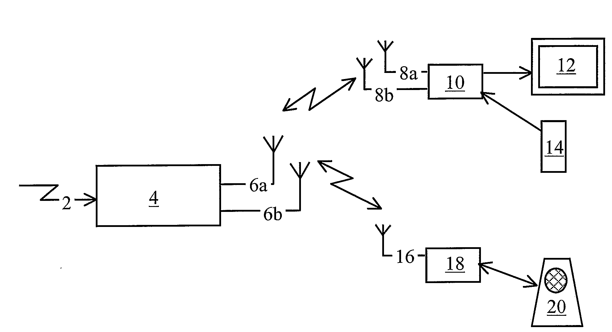
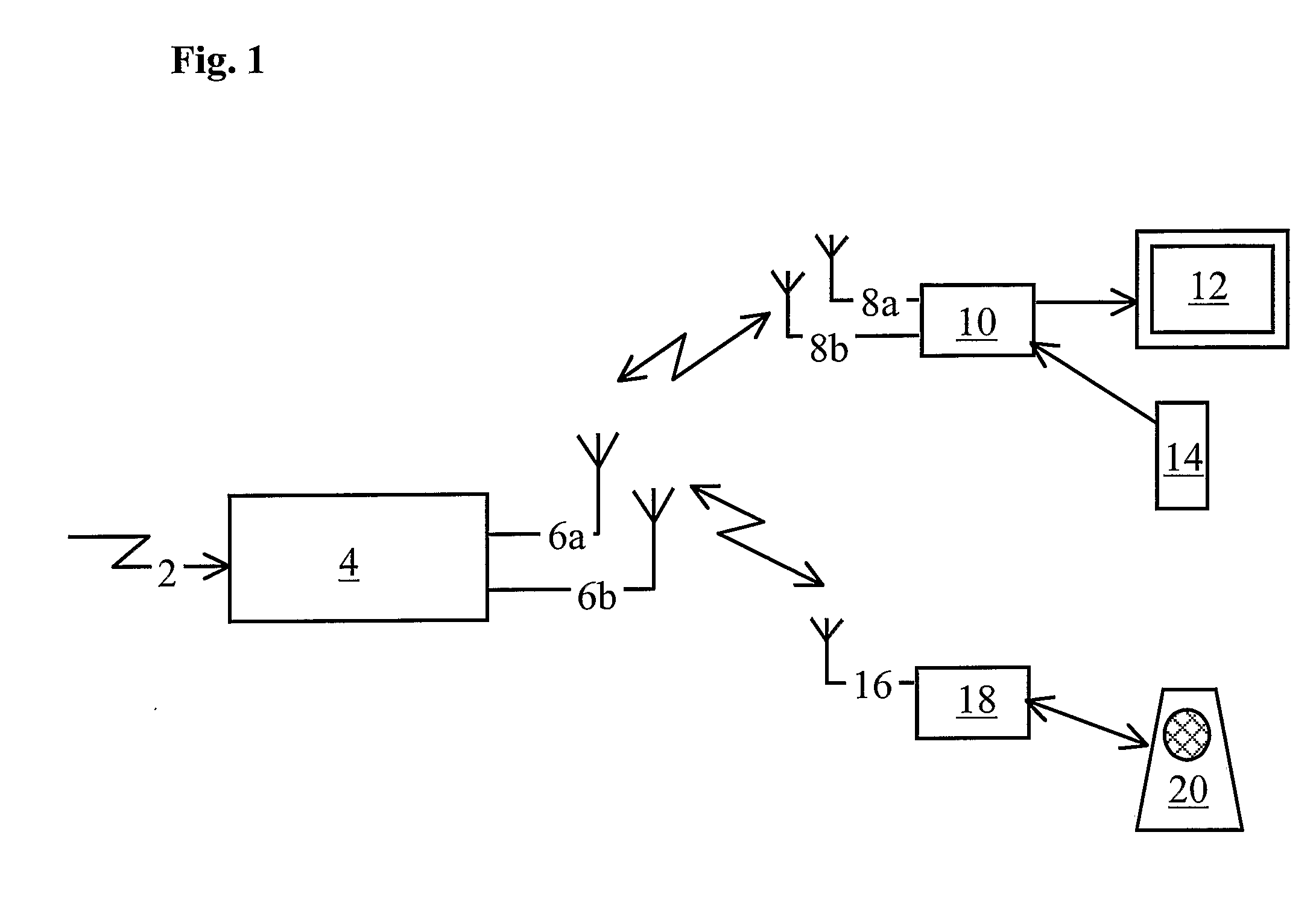
[0035]FIG. 1 shows a wireless network used for local wireless media distribution in an embodiment of the invention. A wireless gateway 4 receives media content from a broadcast link 2. The broadcast link 2 may be a satellite or cable television broadcast link, in which case the wireless gateway includes a satellite or cable television receiver, or a connection to an external network such as a broadband internet connection, in which case the wireless gateway 4 includes an external network adapter such as a broadband modem. The broadcast link may carry one or more media channels, each comprising audio and / or video programmes.

[0036]The wireless gateway 4 is arranged to select one or more of the programmes for storage and / or distribution to one or more wireless receivers 10, 18. In this example, a first wireless receiver 10 is connected to an audiovisual display 12, such as a television, and receives audio and video signals from the wireless gateway 4 ...


PUM


Abstract

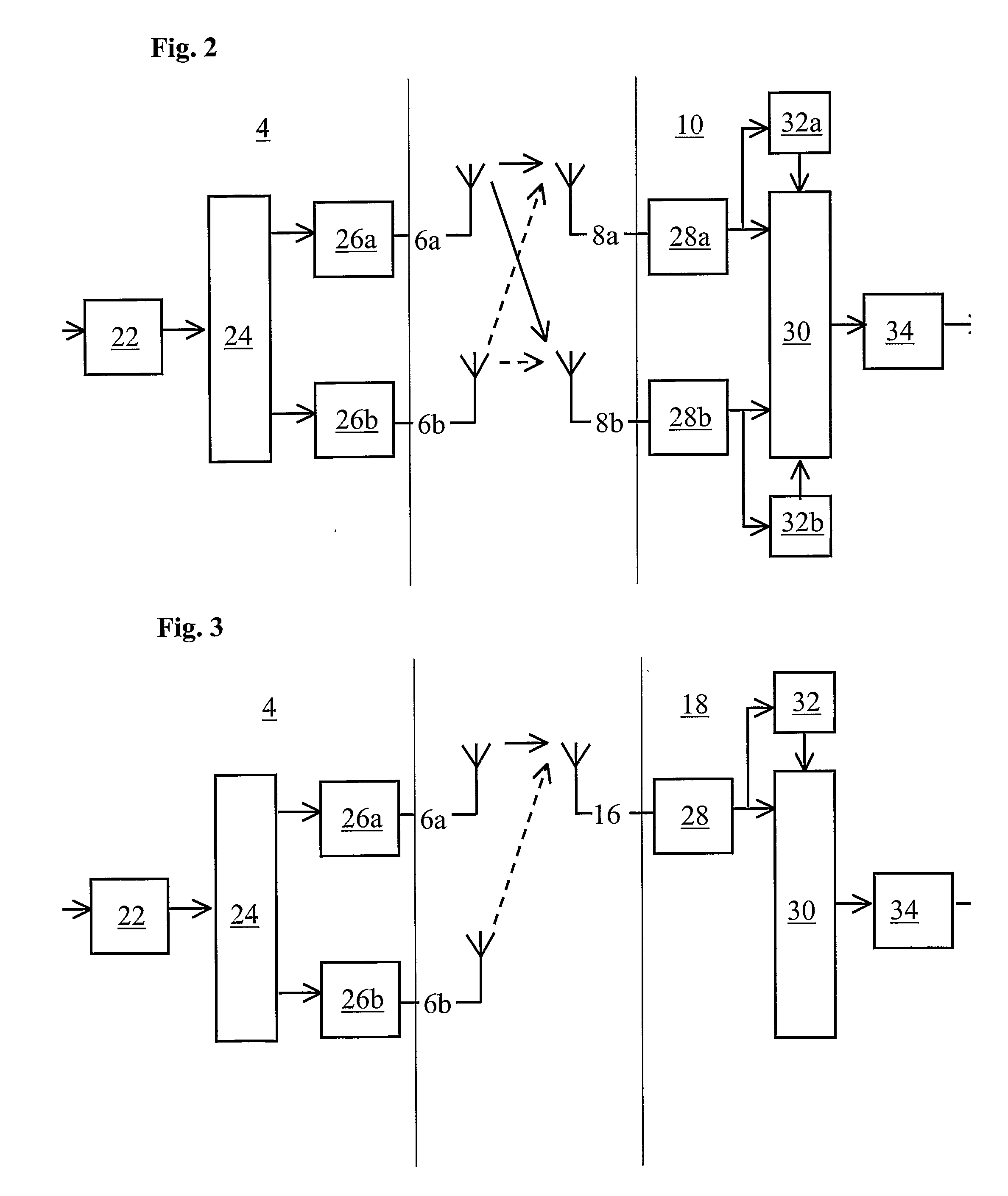
A wireless network device (4), such as a wireless media centre, has orthogonally polarised antennas (6a, 6b) arranged to provide transmit and / or receive polarisation diversity. The antennas may be arranged so that their nulls do not coincide, to produce a combined antenna pattern with a low variation of gain with direction. The antennas may be collocated, but arranged orthogonally. Preferably, the combined antenna pattern is substantially omnidirectional in elevation as well as azimuth. This arrangement provides uniform coverage in a 3D environment. The transmitter may transmit data using polarisation-time block codes. A wireless receiver (10, 18) for use in the wireless network may have either one antenna or two orthogonally polarised antennas. The receiver (10, 18) applies maximal ratio combining to the received signals. The signals may be OFDM signals and the receiver applies maximal ratio combining independently to each frequency channel. The antennas may be flat linear or annular slot antennas, which provide strongly polarised beams and can be integrated within the housing of the devices.

Description

FIELD OF THE INVENTION[0001]The present invention relates to a wireless network system and devices for use in that system, and particularly but not exclusively for transmitting media content over a wireless network. In particular, the invention is applicable to a video broadcast receiver which distributes video content over a wireless local area network (WLAN).BACKGROUND OF THE INVENTION[0002]With the widespread availability of digital media content, there has been intense interest in developing a media centre for storing and playing back a collection of digital media content, such as digitally encoded and compressed audio and video files. In particular, it is desirable to distribute selected media files from a wireless home media centre on demand to wireless audio and video players distributed around the user's house.[0003]Currently, the most widely implemented WLAN standards are the IEEE 802.11 b and g standards, which provide a quoted bit-rate of 11 and 54 Mbps respectively. The ...

Claims


Application Information

Patent Timeline
Patent Type & Authority Applications(United States)
IPC IPC(8): H04N7/16H01Q21/24H04B7/06H04B7/08H04B7/10H04J99/00H04L1/04H04L1/06
CPCH04B7/10H04L1/0618H04L1/04
Inventor NIX, ANDREW R.LILLIE, ANDREW GEORGE
Owner SKY
Learn More