Methods for stripping and modifying surfaces with laser-induced ablation

a technology of laser-induced ablation and surface modification, which is applied in the direction of cleaning using liquids, instruments, manufacturing tools, etc., can solve the problems of reducing the use value of laser-induced ablation, affecting the quality of laser-induced ablation, and affecting the effect of laser-induced ablation on the surface,

Active Publication Date: 2009-01-08
GEN LASERTRONICS
View PDF102 Cites 98 Cited by
  • Summary
  • Abstract
  • Description
  • Claims
  • Application Information

AI Technical Summary

Benefits of technology

[0022]In some embodiments, the surface is composed of materials and/or structures that infrared (IR) laser light used to remove coatings merely passes through without the desired effects. When the surface to be removed is composed of such materials and/or structur

Problems solved by technology

However, current scanning head configurations and methods of removing the coating provide only limited success in achieving uniform coating removal.
Further, current laser-based coating removal techniques are less effective when applied to newer composite materials, such as fiber-reinforced polymer composites.
Although composite materials provide technical advantages in a variety of applications, manufacturers have had to confront several problems in fabricating useful products at an acceptable cost.
These problems include the cleanliness and surface chemistry of the composite material.
In most composite manufacturing processes, mold release agents and ambient hydrocarbon aerosols are deposited on the composite surface as undesirable contaminants.
These contaminants degrade the mechanical properties of adhesive bond joints as well as the adhesion of coatings on the composite surface.
In addition to being inherently labor-intensive, the use of abrasive processes for composite surface preparation entails other disadvantages, including unintended damage to t

Method used


Image

  • Methods for stripping and modifying surfaces with laser-induced ablation
  • Methods for stripping and modifying surfaces with laser-induced ablation
  • Methods for stripping and modifying surfaces with laser-induced ablation

Examples


Embodiment Construction

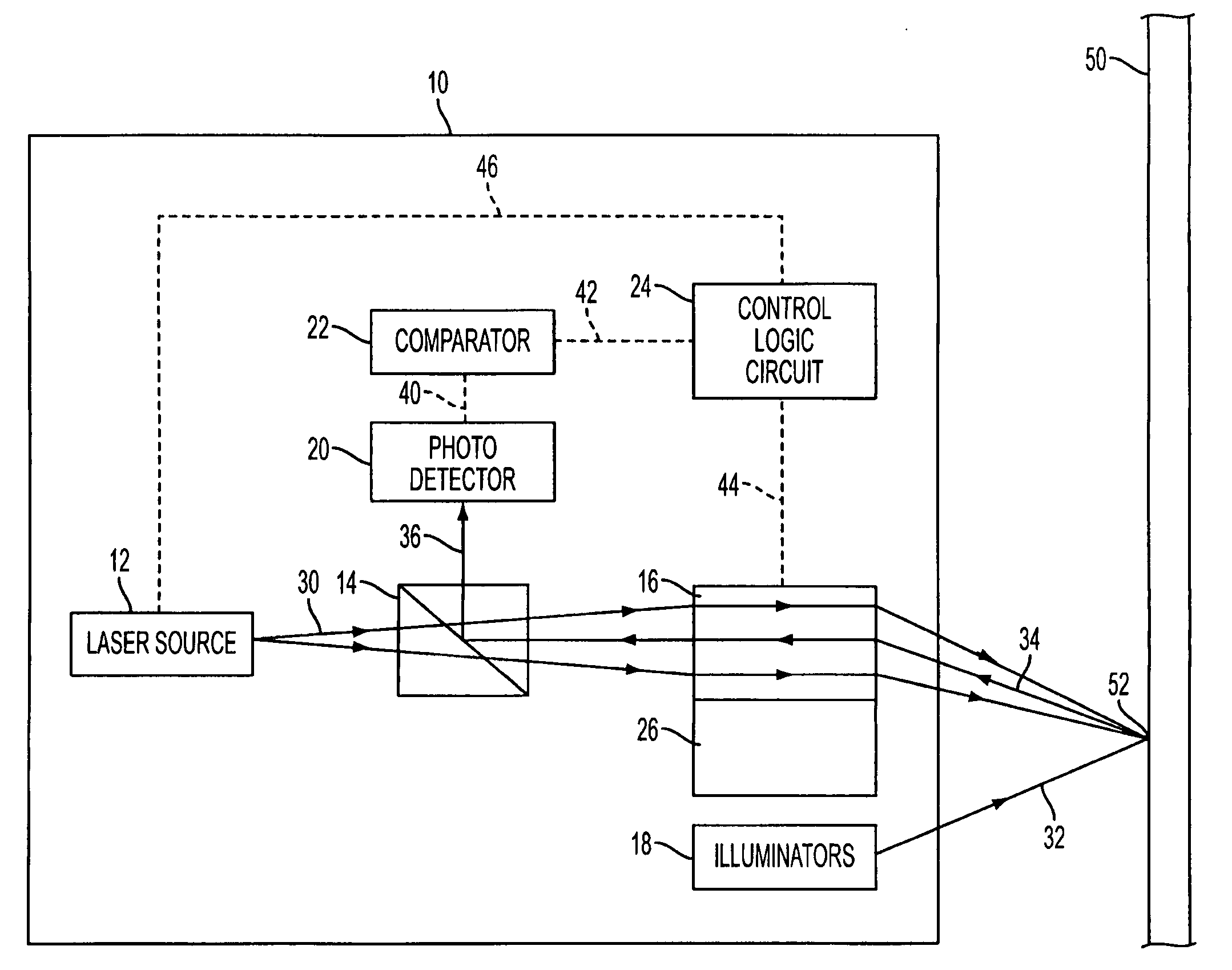
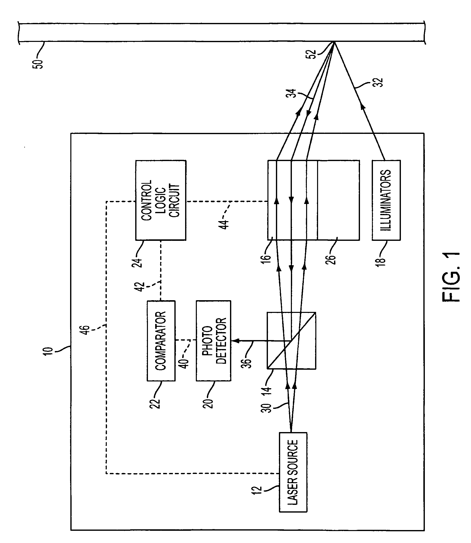
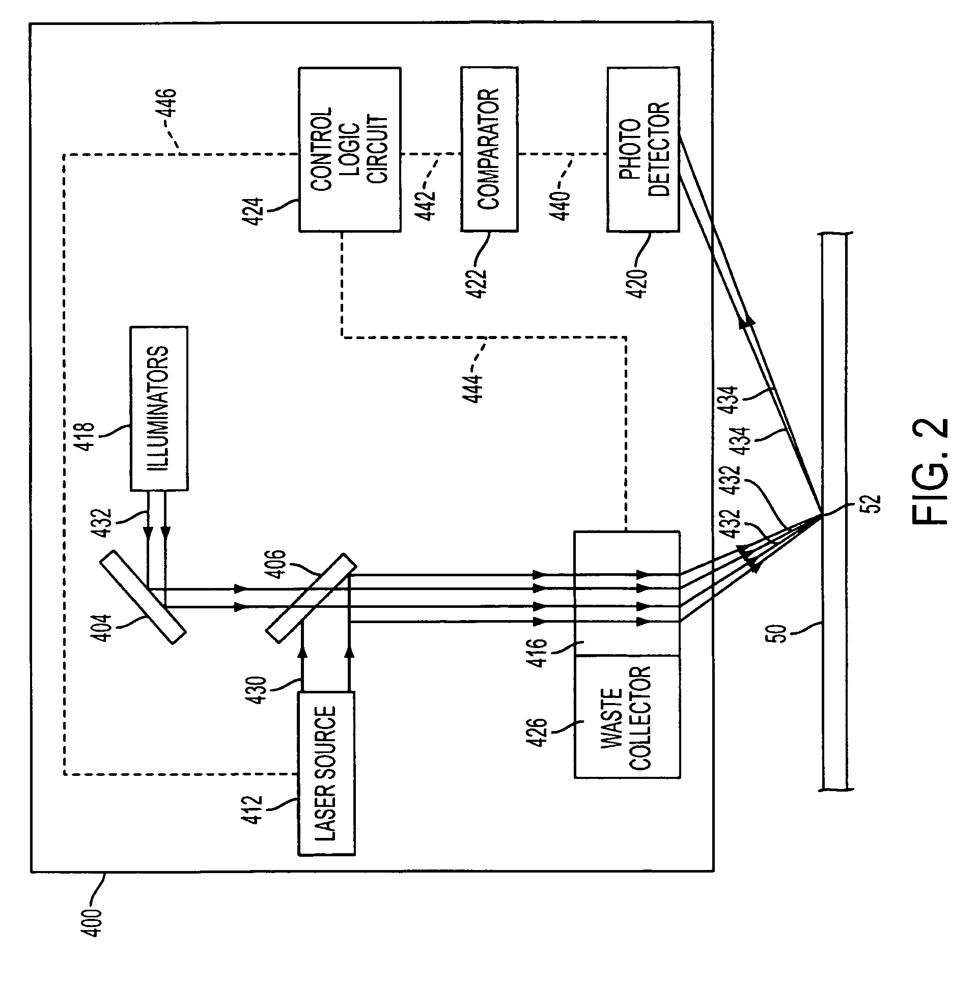
[0041]Embodiments of the coating removal apparatus utilize various optics paths to provide laser pulses to a coated surface, to direct a light illumination to the coated surface, and to direct the reflected light from the coated surface to a photosensitive detector and analyzer. In some embodiments, the apparatus is an integrated device including a laser source, a beam splitter, scanning optics including actuating means for adjusting the scanning optics, a waste removal apparatus, one or more light illuminators, a photosensitive detector, a comparator, and a control logic circuit. In other embodiments, the apparatus is divided into separate components, such as a head component and a body component, each of which is coupled via fiber optic cables and / or power lines.

[0042]FIG. 1 illustrates an exemplary block diagram of a coating removal device according to an embodiment of the present invention. The coating removal device 10 is an integrated device that includes a laser source 12, a ...


PUM

PropertyMeasurementUnit
Depthaaaaaaaaaa
Depthaaaaaaaaaa
Angleaaaaaaaaaa

Abstract

A coating removal apparatus removes a coating from a surface. The apparatus has a movable scanning head and scanning optics. The scanning head is movable in one dimension, and the scanning optics adjust in two dimensions to compensate for movement of the scanning head to implement long range scanning with a uniform scanning pattern. Further, a surface roughness is determined by measuring specular and scattered reflections at various angles. For composite surfaces, the apparatus utilizes UV laser radiation and a controlled atmosphere to remove coating and alter the chemical characteristics at the surface.

Description

RELATED APPLICATIONS[0001]This application claims priority of U.S. provisional application, Ser. No. 60 / 919,707, filed Mar. 22, 2007, and entitled “Preferred Methods for Stripping and Modifying Surfaces with Laser-induced Ablation,” by the same inventors. This application incorporates U.S. provisional application, Ser. No. 60 / 919,707, filed Mar. 22, 2007, and entitled “Preferred Methods for Stripping and Modifying Surfaces with Laser-induced Ablation” in its entirety by reference.[0002]This application also claims priority of U.S. provisional application, Ser. No. 60 / 958,737, filed Jul. 9, 2007, and entitled “Apparatus and method for Ultraviolet Laser Surface Treatment of Composite Materials,” by a common inventor. This application incorporates U.S. provisional application, Ser. No. 60 / 958,737, filed Jul. 9, 2007, and entitled “Apparatus and method for Ultraviolet Laser Surface Treatment of Composite Materials” in its entirety by reference.FIELD OF THE INVENTION[0003]The invention r...

Claims


Application Information

Patent Timeline
IPC IPC(8): B23K26/36
CPCB08B7/0042B23K26/03B23K26/032G01B11/303B23K26/0807B23K26/1405B23K26/0081B23K26/0665B23K26/142B23K26/082B23K26/361G01B11/30B23K26/354B23K26/08B23K26/36B23K26/362
Inventor THOMAS, JAMES W.CARGILL, ROBERT L.WOOL, MITCHELL R.
Owner GEN LASERTRONICS
Why Eureka
Try Eureka