
Eureka
For R&D, Eureka makes reading and utilizing patents & technical documents easy.
Eureka AIR
Designed for self-driven R&D workflows. Generate viable solutions, solve complex R&D challenges, empower your innovation with AI.

Eureka Materials
Designed for material experts only. Revolutionize your material R&D, from search, analyze, to developing new materials.

TechResearch
Generate reliable direction feasibility study reports for your R&D in just a few steps.

TechSeek
Discover and master advanced knowledge NOW. Basics, ideas, possibilities, all at once.

TechMind
As an expert in R&D Theories, TechMind can generates customized viable solutions instantly.

TechRisk
Analyze your overall solution with one click, know your potential R&D risks in advance.

TechMonitor
Get weekly tech updates, stay abreast of the latest tech innovations and key insights.
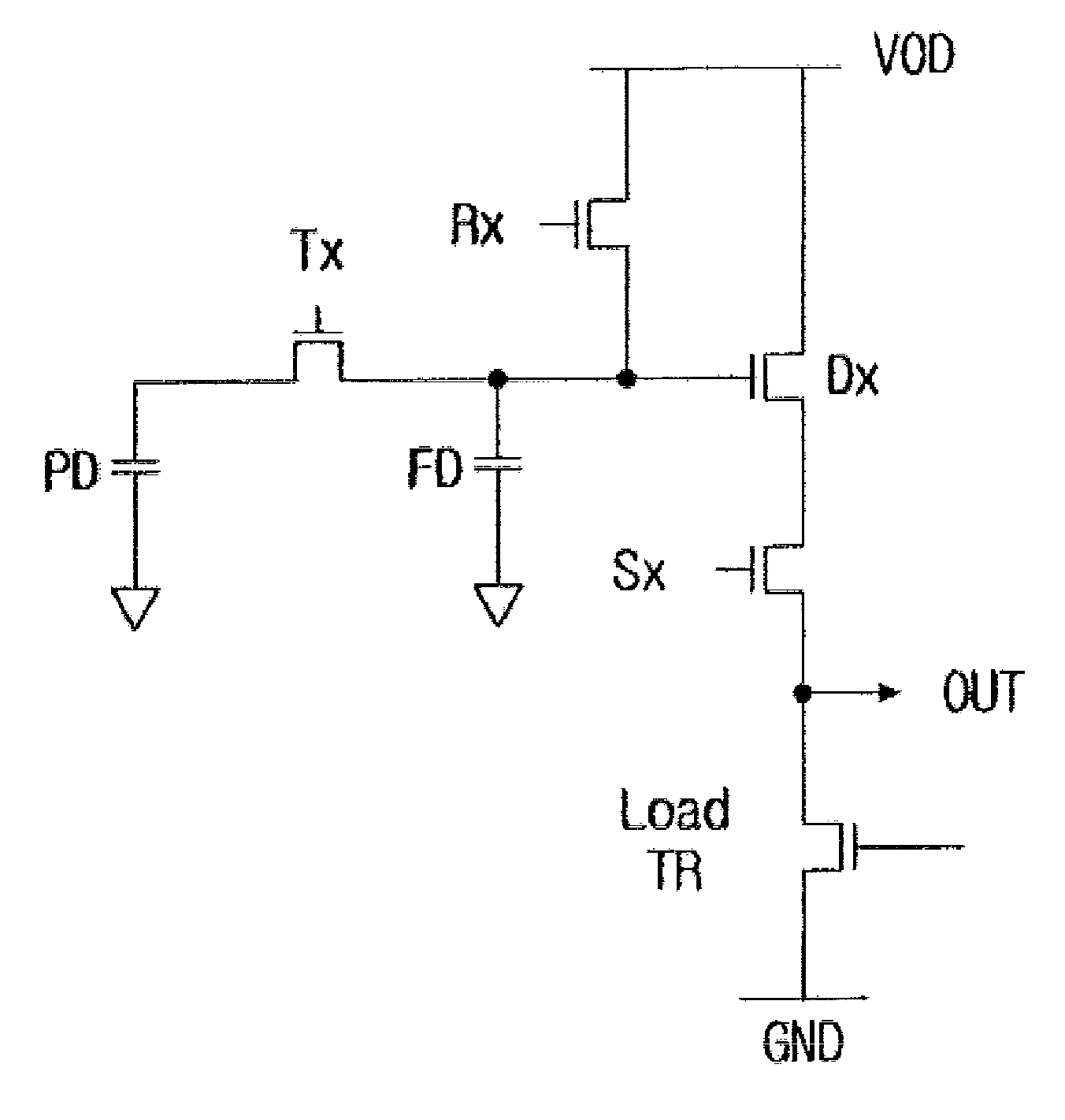
Image Sensor and Controlling Method Thereof
- Summary
- Abstract
- Description
- Claims
- Application Information
AI Technical Summary
Benefits of technology
Problems solved by technology
Method used
Image

Examples
Embodiment Construction
[0036]Hereinafter, embodiments of the present invention will be described in detail with reference to the accompanying drawings.
[0037]The descriptions set forth below merely illustrate the principles of the present invention. Therefore, those skilled in the art could devise various methods and apparatus thereof which realize the principles of the present invention and which do not depart from the spirit and scope of the present invention, even though they may not be clearly explained or illustrated in the present specification. Also, it is to be appreciated that not only the principles, viewpoints, and embodiments of the present invention, but all detailed descriptions listing the particular embodiments are intended to include structural and functional equivalents.
[0038]Terms used in the description (for example, a first, a second, etc.) are merely used to distinguish equal or similar items in an ordinal manner.
[0039]Also, the terms used in the description are merely used to describ...
PUM
 Abstract
Description
Claims
Application Information
 - R&D Engineer
- R&D Manager
- IP Professional
- Industry Leading Data Capabilities
- Powerful AI technology
- Patent DNA Extraction
Browse by: Latest US Patents, China's latest patents, Technical Efficacy Thesaurus, Application Domain, Technology Topic, Popular Technical Reports.
© 2024 PatSnap. All rights reserved.Legal|Privacy policy|Modern Slavery Act Transparency Statement|Sitemap|About US| Contact US: help@patsnap.com