
Steady state frequency control of variable frequency switching regulators

a variable frequency switching and steady state technology, applied in the direction of dc-dc conversion, oscillation generator, power conversion system, etc., can solve the problems of poor steady state frequency control of variable frequency switching regulators, affecting the operating frequency of conventional regulators, inaccurate time constants,

Active Publication Date: 2009-01-08
INTERSIL INC
View PDF13 Cites 58 Cited by
  • Summary
  • Abstract
  • Description
  • Claims
  • Application Information

AI Technical Summary

Benefits of technology

[0016]The frequency control parameter may be a window current, where the method may include multiplying the window current by the frequen

Problems solved by technology

Many variable frequency switching regulators exhibit poor CCM steady state frequency control despite attempts to control the steady state frequency with open loop circuits.
It has been a challenge, therefore, to accurately control the steady-state frequency of variable frequency switching regulators.
Various factors tend to affect the operating frequency of conventional regulators, such as inaccurate input voltage or output voltage sensing, changes of the loop compensation, changes of the output filter, comparator and driver propagation delays, inaccurate time constant matching, load changes (particularly for constant on-time switching devices), etc.
Input voltage sensing is especially poor on devices that sample and hold the voltage of the phase pin to indirectly sense the input voltage.
An error amplifier with high bandwidth causes excessive ripple on the compensation signal, which causes the switching frequency to change with changes of the loop compensation or output filter.
Although various regulator controllers employ extensive open loop circuitry in an attempt to stabilize the steady state switching frequency, the switching frequency control has still been poor.

Method used


Image

  • Steady state frequency control of variable frequency switching regulators
  • Steady state frequency control of variable frequency switching regulators
  • Steady state frequency control of variable frequency switching regulators

Examples


Embodiment Construction

[0027]The following description is presented to enable one of ordinary skill in the art to make and use the present invention as provided within the context of a particular application and its requirements. Various modifications to the preferred embodiment will, however, be apparent to one skilled in the art, and the general principles defined herein may be applied to other embodiments. Therefore, the present invention is not intended to be limited to the particular embodiments shown and described herein, but is to be accorded the widest scope consistent with the principles and novel features herein disclosed.

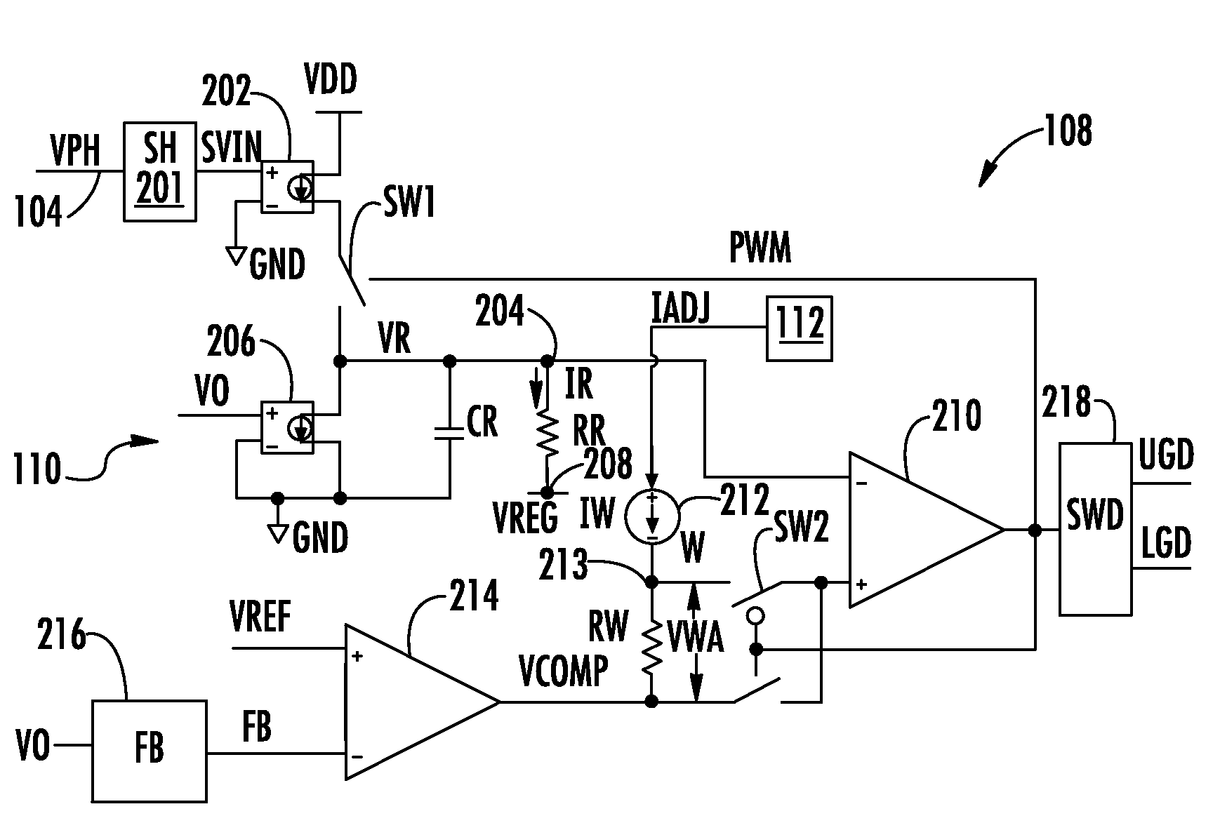
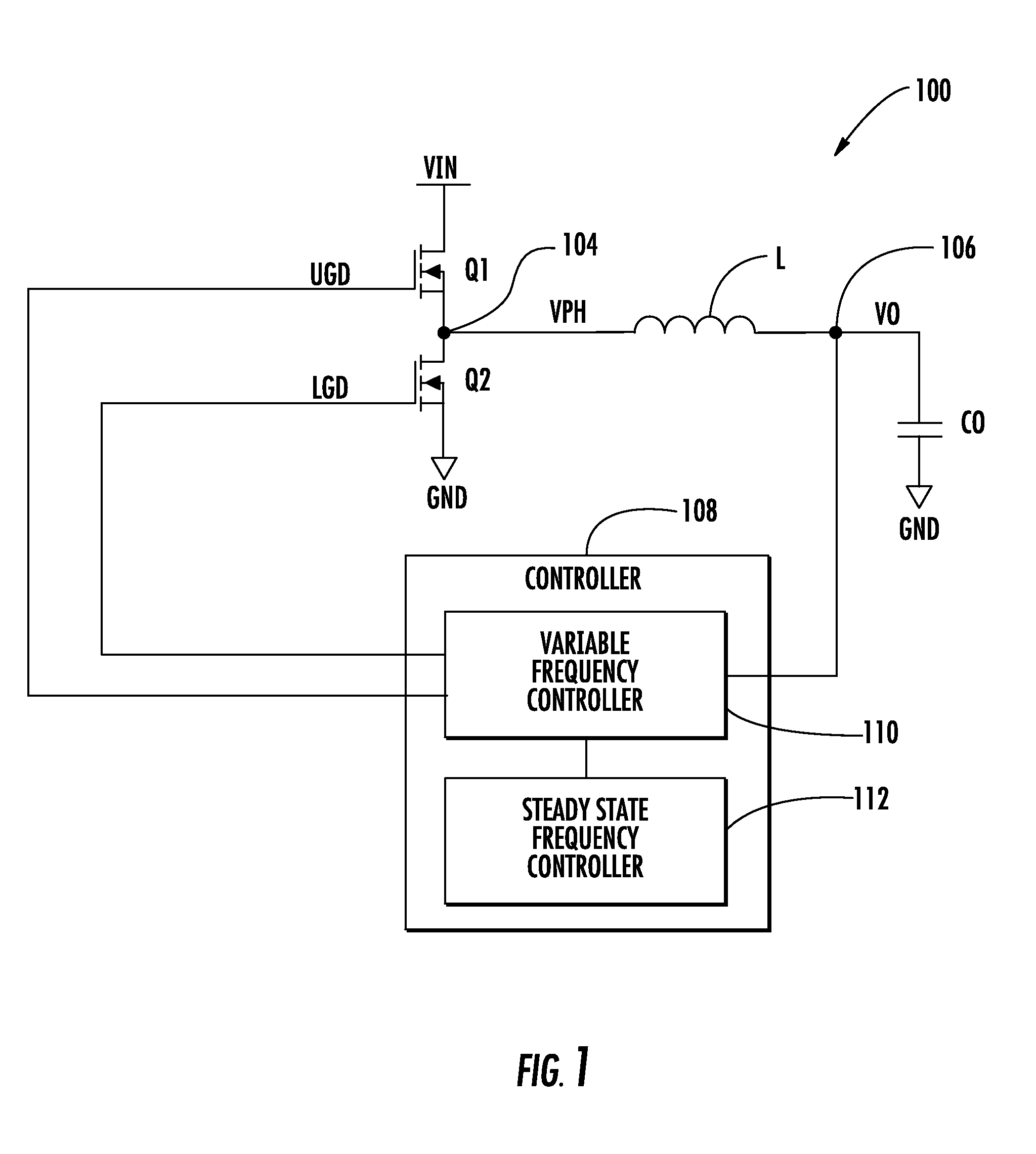
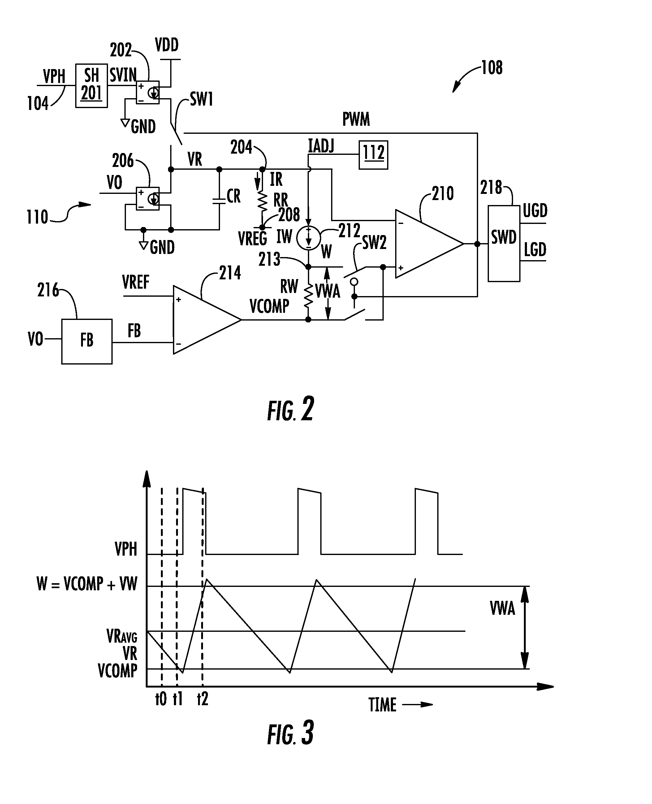
[0028]FIG. 1 is a simplified schematic and block diagram of a buck-type variable frequency regulator 100 including a steady state frequency controller 112 implemented according to one embodiment. A controller 108 provides an upper gate drive signal UGD to a gate terminal of upper switch Q1 and provides a lower gate drive signal LGD to a gate terminal of lower switch Q2. In the ...


PUM


Abstract

A steady state frequency control circuit for a variable frequency regulator including an open loop frequency control circuit, a frequency detector and a comparator circuit. The variable frequency regulator provides a clock signal indicating actual operating frequency and has a frequency control parameter for adjusting steady state operating frequency. The frequency detector receives the clock signal and provides a frequency sense signal which is compared with a steady state frequency reference signal to provide a frequency adjust signal. The frequency control parameter is adjusted by the frequency adjust signal to control steady state frequency. A method of controlling steady state frequency of a variable frequency regulator includes using open loop frequency control, determining the operating frequency and providing a frequency sense signal, comparing the frequency sense signal with frequency reference signal and providing a frequency adjust signal, and adjusting the frequency control parameter based on the frequency adjust signal.

Description

BACKGROUND OF THE INVENTION[0001]1. Field of the Invention[0002]The present invention relates to power electronics and variable frequency switching regulators, and more particularly to open and closed loop steady state frequency control of variable frequency switching regulators.[0003]2. Description of the Related Art[0004]Variable frequency switching architectures, such as, for example, synthetic ripple regulators, hysteretic regulators, constant on / off switching regulators, etc., are popular solutions for buck-type switching regulators used in various electronic devices, such as notebook computers and the like. Such topologies have the ability to respond quickly to transient events (e.g., significant load changes) without having to wait for a clock pulse or the like. Generally, such regulators operate in continuous conduction mode (CCM) at moderate to heavy loads and discontinuous conduction mode (DCM) at light loads. System designers prefer fixed frequencies in CCM so that filter...

Claims


Application Information

Patent Timeline
IPC IPC(8): G05F1/10H03B19/00
CPCH02M3/156
Inventor PHILBRICK, RHYS S.A.
Owner INTERSIL INC
Learn More