

Liquid Crystal Composition, Optical Compensation Film and Liquid Crystal Display Device
a liquid crystal display and composition technology, applied in the field of liquid crystal composition, optical compensation film and liquid crystal display device, can solve the problems of lowering display quality, reducing contrast, and reducing display quality, so as to enhance contrast, reduce contrast, and reduce contrast
- Summary
- Abstract
- Description
- Claims
- Application Information
AI Technical Summary
Benefits of technology
Problems solved by technology
Method used
Image

Examples
example 1
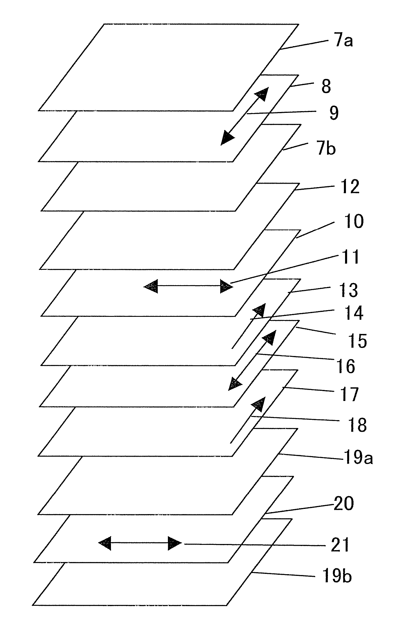
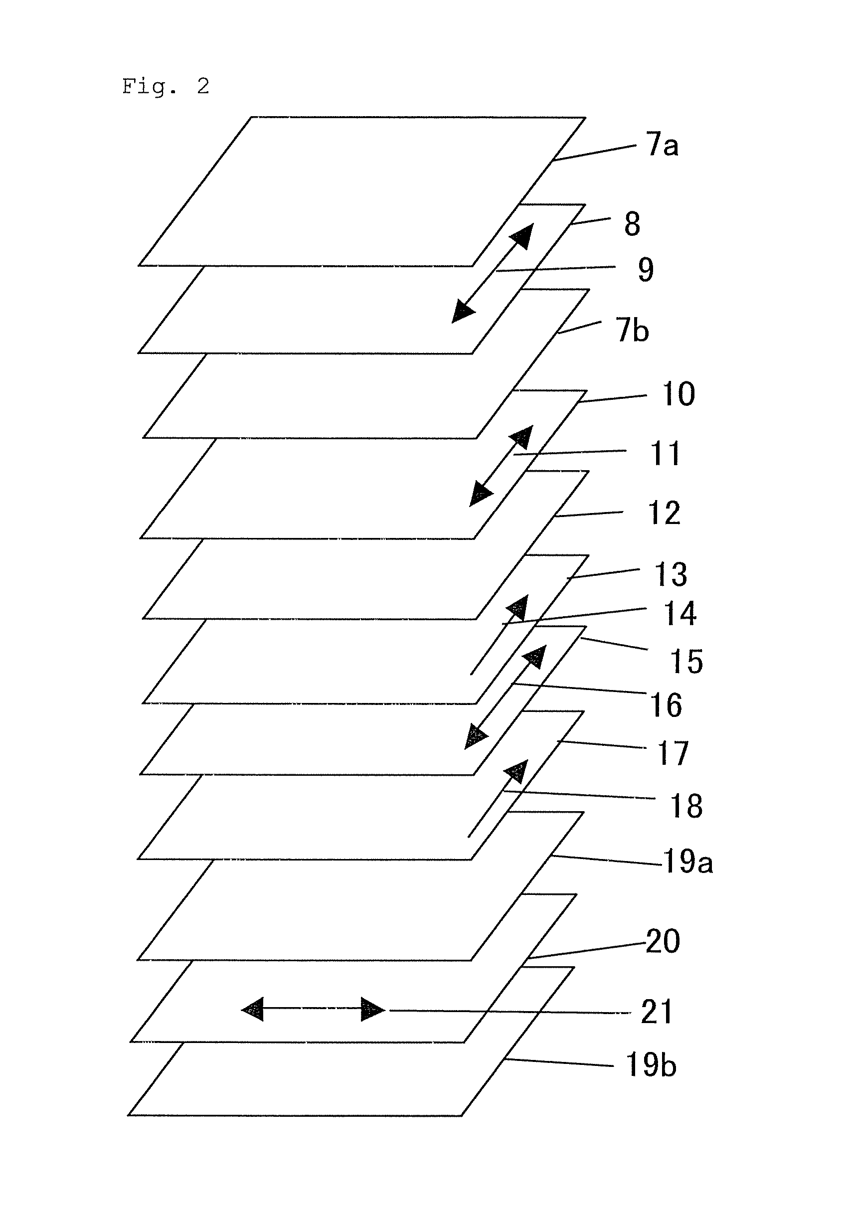
[0274]The retardation film 1 as prepared previously was stuck onto the polarizing plate A in the side of the polarizing film, onto which the cellulose acetate film was not stuck, using a polyvinyl alcohol based adhesive so that the first retardation region 1 was disposed at the polarizing film side and the transmission axis of the polarizing film and the slow axis of the first retardation region 1 were parallel to each other, thereby forming a polarizing plate 1.
[0275]This polarizing plate 1 was stuck onto one side of the IPS mode liquid crystal cell 1 as prepared previously so that the slow axis of the first retardation region 1 was parallel to the rubbing direction of the liquid crystal cell (namely, the slow axis of the first retardation region 1 was parallel to the slow axis of the liquid crystal molecules of the liquid crystal cell in a black state) and the second retardation region 1 was disposed at the liquid crystal cell side.
[0276]Subsequently, the polarizing plate C was st...
example 2
[0277]The retardation film 2 as prepared previously was stuck onto the polarizing plate A in the side of the polarizing film, onto which the cellulose acetate film was not stuck, using a polyvinyl alcohol based adhesive so that the first retardation region 1 was disposed at the polarizing film side and the transmission axis of the polarizing film and the slow axis of the first retardation region 1 were parallel to each other, thereby forming a polarizing plate 2.
[0278]This polarizing plate 2 was stuck onto one side of the IPS mode liquid crystal cell 1 as prepared previously so that the slow axis of the first retardation region 1 was parallel to the rubbing direction of the liquid crystal cell (namely, the slow axis of the first retardation region 1 was parallel to the slow axis of the liquid crystal molecules of the liquid crystal cell in a black state) and the second retardation region 2 was disposed at the liquid crystal cell side.
[0279]Subsequently, the polarizing plate D was st...
example 3
[0280]The retardation film 3 as prepared previously was stuck onto the polarizing plate B using an acrylic resin based adhesive so that the second retardation region 3 was disposed at the polarizing film side and the transmission axis of the polarizing film and the slow axis of the first retardation region 2 were orthogonal to each other, thereby forming a polarizing plate 3.
[0281]This polarizing plate 3 was stuck onto one side of the IPS mode liquid crystal cell 1 as prepared previously so that the slow axis of the first retardation region 2 was orthogonal to the rubbing direction of the liquid crystal cell (namely, the slow axis of the first retardation region 2 was orthogonal to the slow axis of the liquid crystal molecules of the liquid crystal cell in a black state) and the first retardation region 2 was disposed at the liquid crystal cell side.
[0282]Subsequently, the polarizing plate C was stuck onto the other side of the IPS mode liquid crystal cell 1 so that the polarizing p...
PUM
| Property | Measurement | Unit |
|---|---|---|
| wavelength | aaaaa | aaaaa |
| refractive index | aaaaa | aaaaa |
| thickness | aaaaa | aaaaa |
Abstract
Description
Claims
Application Information