Honeycomb structure and bonding material to be used for same

Active Publication Date: 2009-01-08
NGK INSULATORS LTD +1
View PDF13 Cites 32 Cited by
  • Summary
  • Abstract
  • Description
  • Claims
  • Application Information

AI Technical Summary

Benefits of technology

[0041]In the honeycomb structure of the present invention, a bonding material constituted of a component in which any influence on the health of a human body does not have to be considered is dried to form a bonding layer, and outer walls are bonded to one another via thes

Problems solved by technology

The honeycomb structure used in this manner has a problem such that a temperature distribution in the honeycomb structure becomes nonuniform owing to the rapid temperature change of the exhaust gas or local heat generation, and thereby cracks are generated in the honeycomb structure.
In this case, local temperature rise is caused, which results in problems that a regeneration efficiency lowers owing to the nonuniformity of a regeneration temperature and that the cracks due to a large thermal stress are easily generated.
As a result, the ceramic honeycomb structure might incur the crack generation or melting.
For example, bonding layers are cracked owing to the difference of the thermal expansion ratio or a contraction rati

Method used


Image

  • Honeycomb structure and bonding material to be used for same
  • Honeycomb structure and bonding material to be used for same
  • Honeycomb structure and bonding material to be used for same

Examples


examples

[0081]The present invention will hereinafter specifically be described in accordance with examples, but the present invention is not limited to these examples.

[0082]1. Manufacturing of Honeycomb Segment:

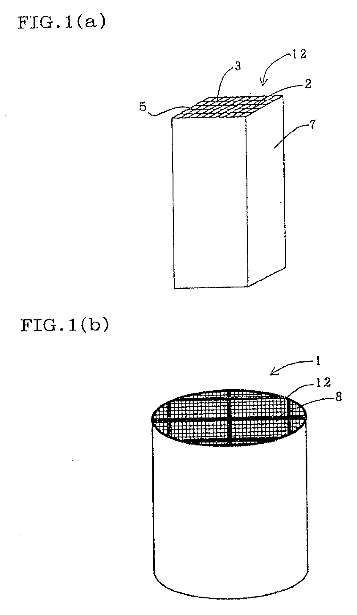
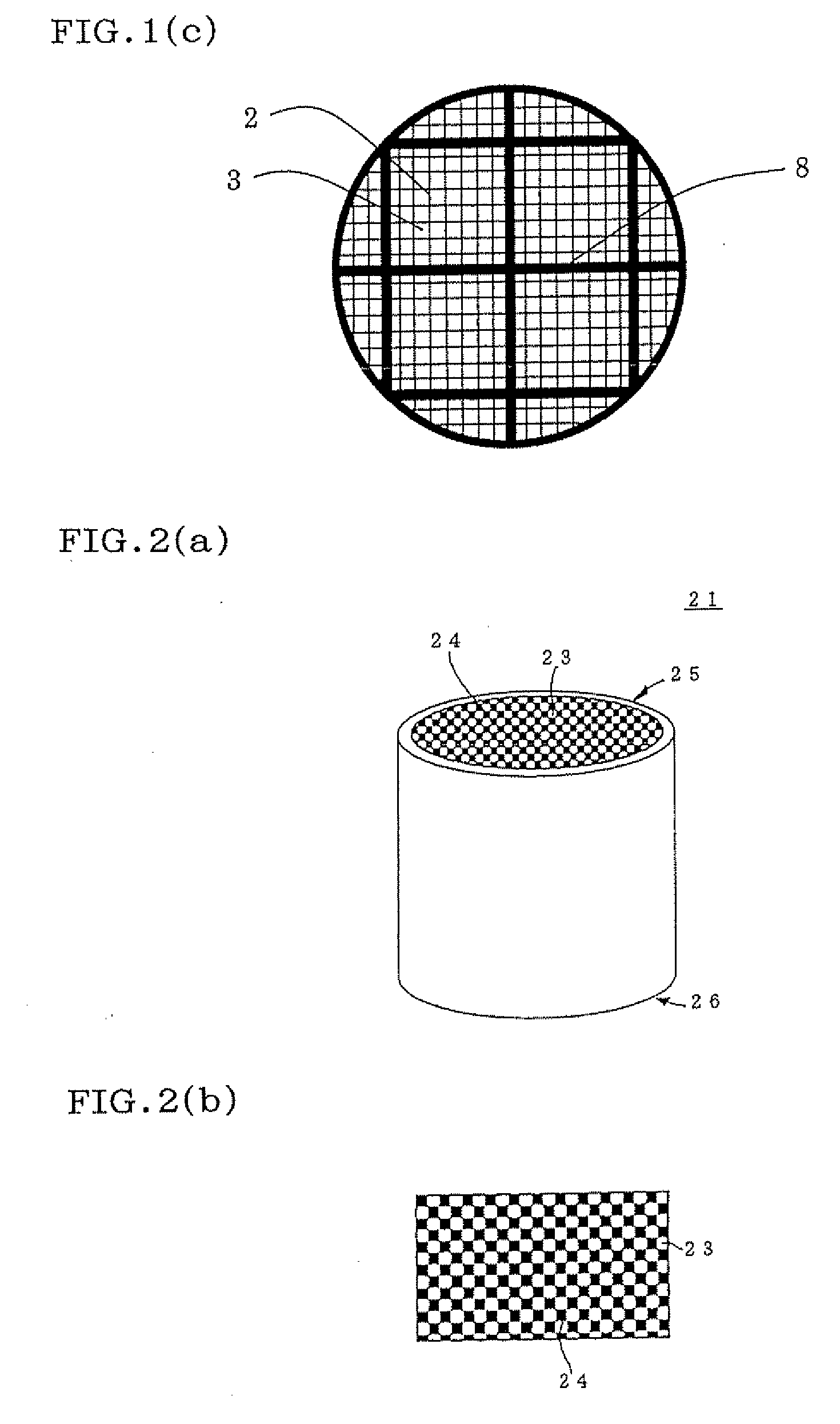
[0083]As a honeycomb segment raw material, SiC powder and metal Si powder were mixed at a mass ratio of 80:20, and starch and a foam resin as pore formers, further methyl cellulose, hydroxypropoxyl methyl cellulose, a surfactant, and water were added to the material to prepare a plastic clay. This clay was extruded, formed, and dried by microwaves and hot air to obtain a honeycomb segment formed body including partition walls having a thickness of 310 μm, having a cell density of about 46.5 cells / cm2 (300 cells / square inch), having a square section with each 35 mm long side and having a length of 152 mm. In this honeycomb segment formed body, both end faces of the cells were plugged so that the end faces had a checkered pattern. That is, the cells were plugged so that adjacent cells ...

examples 7 to 27

[0093]Subsequently, 16 honeycomb segments were bonded to one another by use of bonding materials (bonding materials A-1 to A-18) shown in Tables 5 and 6, and dried at 200° C. for 2 hours. Afterward, an outer peripheral portion was ground so as to obtain a cylindrical shape, and the corresponding portion was coated with a coating material, and subjected to a thermal treatment at 500° C. for 2 hours, to obtain honeycomb structures (Examples 7 to 27).

TABLE 54-pointCompressionThermalBondingbendingYoung'sThermalexpansionThermalmaterialBondingstrengthmodulusconductivitycoefficientcapacitythicknessB-SPE-SPE / Gmaterial[kPa][MPa][W / mK][×10−6][m−3 / K][mm]testtesttestExample 7A-16002001.04.510001 800° C.⊚⊚Example 8A-25501500.74.58001 900° C.⊚⊚Example 9A-34001300.54.57001 850° C.⊚⊚Example 10A-4900800.64.580011000° C.⊚⊚Example 11A-51000500.54.580011100° C.⊚⊚Example 12A-61000500.54.580011100° C.⊚⊚Example 13A-7500800.54.58001 800° C.⊚⊚Example 14A-8500800.54.58001 800° C.⊚⊚Example 15A-91000801.54.511...


PUM

PropertyMeasurementUnit
Temperatureaaaaaaaaaa
Percent by massaaaaaaaaaa
Thicknessaaaaaaaaaa

Abstract

There is disclosed a honeycomb structure 1 which is made of a ceramic material and in which a plurality of honeycomb segments 12 having cell structures 5 and porous outer walls 7 on outer peripheries of the cell structures 5 are integrated by bonding the outer walls 7 to one another with a bonding material, each of the cell structures being provided with a plurality of cells 3 constituting fluid channels divided by porous partition walls 2, wherein the bonding material contains a bio-soluble fiber. The honeycomb structure 1 of the present invention has a performance equivalent to that of a honeycomb structure in which a heretofore used ceramic fiber is contained.

Description

TECHNICAL FIELD[0001]The present invention relates to a honeycomb structure and a bonding material for use in the structure. More particularly, it relates to a honeycomb structure which contains a bio-soluble fiber, whereby environmental safety is improved.BACKGROUND ART[0002]A honeycomb structure made of a ceramics has been used in a catalyst carrier for an internal combustion engine, a boiler, a chemical reaction device, a reformer for a fuel cell and the like in which a catalyst function is used, a trapping filter of fine particles in an exhaust gas, particularly diesel fine particles (a diesel particulate filter, hereinafter sometimes referred to as the “DPF”), and the like.[0003]In general, as shown in FIGS. 2(a) and 2(b), a honeycomb structure for use in such purposes has a structure which includes a plurality of cells 23 constituting fluid channels divided by porous partition walls 24 and in which adjacent cells 23 are alternatively plugged on the opposite end portions so tha...

Claims


Application Information

Patent Timeline
IPC IPC(8): B32B3/12
CPCY10T428/24149C04B35/806C04B2237/365C04B2237/083C04B2237/064C04B2235/9607C04B2235/96B01D39/2075B01D46/2425B01D46/2444B01D46/2448B01D46/2459B01D46/2466B01D2046/2433B01D2239/08B01J35/04C04B28/24C04B35/117C04B35/565C04B35/6303C04B35/6316C04B35/803C04B2237/708C04B37/005C04B38/0006C04B38/0019C04B2111/00793C04B2111/0081C04B2235/3418C04B2235/349C04B2235/3826C04B2235/428C04B2235/5224C04B2235/5228C04B2235/5232C04B2235/526C04B2235/5264C04B2235/5436C04B2235/77C04B14/043C04B14/303C04B14/324C04B14/328C04B14/4643C04B24/383C04B38/08C04B35/80C04B38/0054C04B38/0074C04B38/0645B01D46/24491B01D46/24494B01D46/2482B01D46/2478B01D46/24495B01D53/94C04B37/00
Inventor MASUKAWA, NAOSHIWATANABE, ATSUSHIICHIKAWA, SHUICHIYAMAKAWA, OSAMUHONJO, TETSUHIRO
Owner NGK INSULATORS LTD
Why Eureka
Try Eureka