Hydrogen generating apparatus and fuel cell power generation system

a technology of hydrogen generating apparatus and which is applied in electrochemical generators, chemical/physical/physico-chemical processes, physical/chemical process catalysts, etc., can solve the problems of large volume, high cost, and low storage efficiency, and achieve the effect of increasing the efficiency of the fuel cell power generation system

Inactive Publication Date: 2009-01-08
SAMSUNG ELECTRO MECHANICS CO LTD
View PDF4 Cites 2 Cited by
  • Summary
  • Abstract
  • Description
  • Claims
  • Application Information

AI Technical Summary

Benefits of technology

[0019]An aspect of the invention provides a hydrogen generating apparatus and a fuel cell power generation system, in which overflowing of the reagents in the hydrogen generation reaction can be prevented, to increase the efficiency of the fuel cell power generation system.

Problems solved by technology

Using a hydrogen storage tank, etc., for supplying the hydrogen can result in a large volume and can require special care in handling and keeping.
Because hydrogen exists as a gas at normal temperature, it entails very low storage efficiency.
Using a pressurized tank for storing hydrogen may result in a very large volume for the fuel tank, whereas using an alloy for hydrogen storage may result in a very high mass.
As such, the use of a hydrogen storage means may result in an increased size or mass of the overall fuel cell system, and thus may be difficult to utilize in portable electronic devices.
In methods of supplying a fuel cell with hydrogen, the method of injecting hydrogen directly may be advantageous in terms of reducing energy losses, but due to difficulties in storing hydrogen as well as the safety hazards involved, this method is employed only in a limited number of fields, including fields of transport vehicles and power generation.
With this method, however, when the hydrogen generated inside the reactor is transferred to the fuel cell, water, which is one of the reagents, may be transferred as a vapor together with the hydrogen, to dramatically lower the efficiency of the fuel cell.

Method used


Image

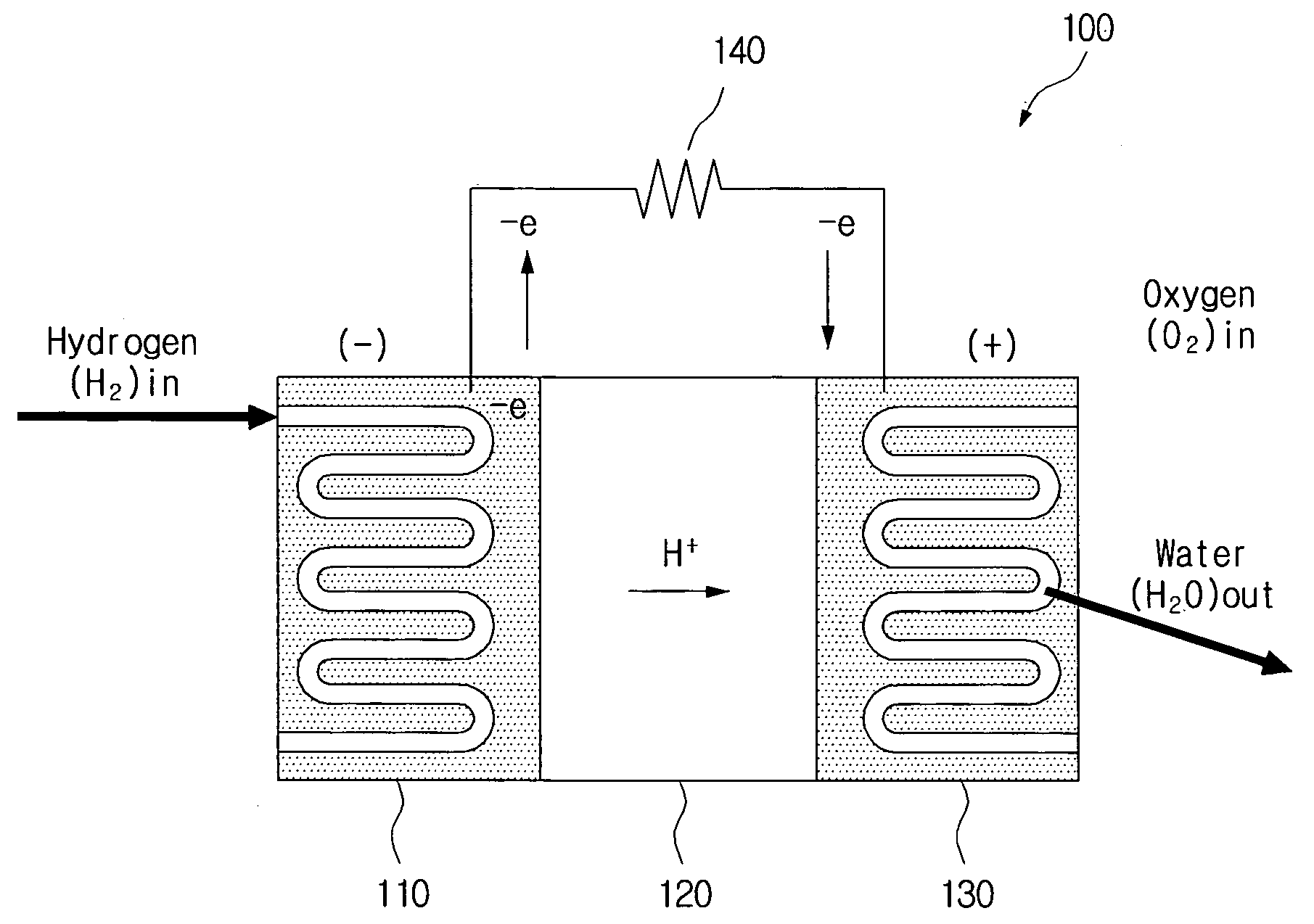
  • Hydrogen generating apparatus and fuel cell power generation system
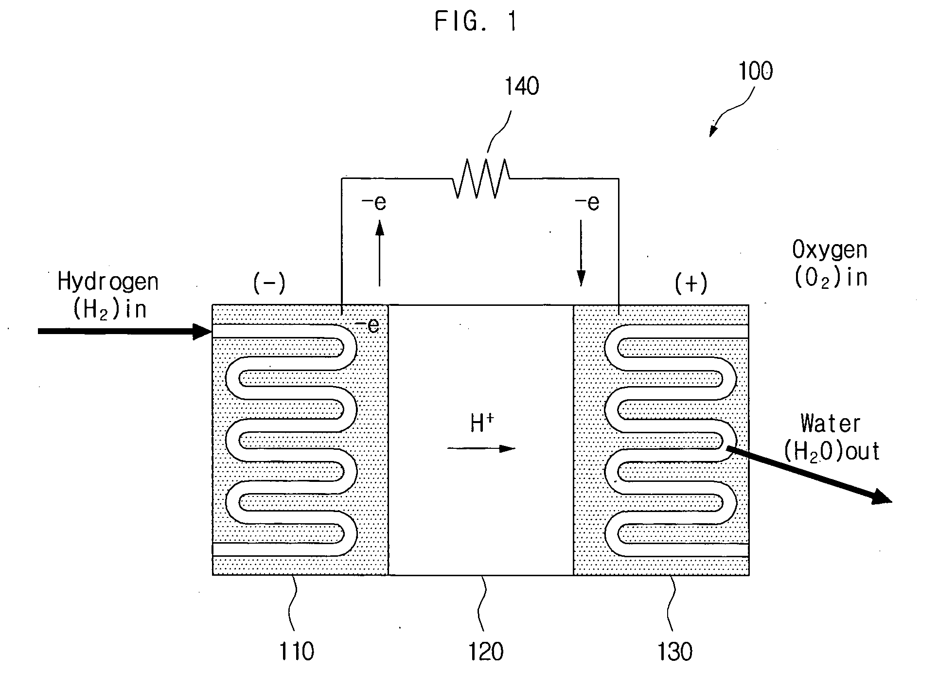
  • Hydrogen generating apparatus and fuel cell power generation system
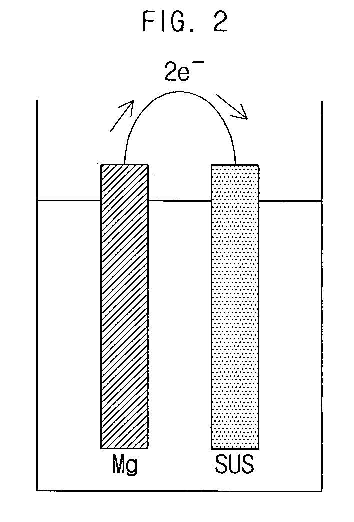
  • Hydrogen generating apparatus and fuel cell power generation system

Examples


Embodiment Construction

[0035]As the invention allows for various changes and numerous embodiments, particular embodiments will be illustrated in drawings and described in detail in the written description. However, this is not intended to limit the present invention to particular modes of practice, and it is to be appreciated that all changes, equivalents, and substitutes that do not depart from the spirit and technical scope of the present invention are encompassed in the present invention. In the description of the present invention, certain detailed explanations of related art are omitted when it is deemed that they may unnecessarily obscure the essence of the invention.

[0036]While such terms as “first” and “second,” etc., may be used to describe various components, such components must not be limited to the above terms. The above terms are used only to distinguish one component from another. For example, a first component may be referred to as a second component without departing from the scope of rig...


PUM

PropertyMeasurementUnit
adhesionaaaaaaaaaa
chemical energyaaaaaaaaaa
electrical energyaaaaaaaaaa

Abstract

A hydrogen generating apparatus and a fuel cell power generation system. An aspect of the invention provides a hydrogen generating apparatus for generating hydrogen through a dissociation reaction of an aqueous solution using electrons formed by an ionization of a metal. The hydrogen generating apparatus can include a chamber, which contains the aqueous solution, and in one side of which an outlet is formed to discharge the hydrogen; and a membrane, which is formed inside the chamber adjacent to the outlet, and which selectively permits the passage of the hydrogen. With certain embodiments of the invention, the overflowing of reagents can be prevented, for higher efficiency in the fuel cell. Because of the improvement in efficiency of the fuel cell power generation system, the volume of the system can be reduced, allowing for easier application to mobile devices.

Description

CROSS-REFERENCE TO RELATED APPLICATIONS[0001]This application claims the benefit of Korean Patent Application No. 10-2007-0066055 filed with the Korean Intellectual Property Office on Jul. 2, 2007, the disclosure of which is incorporated herein by reference in its entirety.BACKGROUND[0002]1. Technical Field[0003]The present invention relates to a hydrogen generating apparatus and a fuel cell power generation system.[0004]2. Description of the Related Art[0005]A fuel cell is an apparatus that converts the chemical energies of fuel (hydrogen, LNQ LPQ methanol, etc.) and air directly into electricity and heat, by means of electrochemical reactions. In contrast to conventional power generation techniques, which employ the processes of burning fuel, generating vapor, driving turbines, and driving power generators, the utilization of fuel cells does not entail combustion processes or driving apparatus. As such, the fuel cell is an attractive new technology for generating power that offers...

Claims


Application Information

Patent Timeline
Patent Type & Authority Applications(United States)
IPC IPC(8): H01M8/18B01J19/00
CPCC01B3/04C01B3/501C01B2203/041C01B2203/0495Y02E60/528H01M8/0656H01M8/186H01M16/003Y02E60/364C01B2203/066Y02E60/36Y02E60/50H01M8/04
Inventor CHA, HYE-YEONOH, YOUNG-SOOJANG, JAE-HYUKJUNG, CHANG-RYULKU, BO-SUNG
Owner SAMSUNG ELECTRO MECHANICS CO LTD
Why Eureka
Try Eureka