
Drilling fluid composition comprising hydrophobically associating polymers and methods of use thereof

a technology of hydrophobic association and fluid composition, which is applied in the direction of drilling composition, borehole/well accessories, petroleum industry, etc., can solve the problems of bitumen sticking to the drilling components, high torque and drag, and the problem of bitumen accretion or sticking is known to occur, so as to prevent the dispersal of bitumen, the effect of less sticking

Active Publication Date: 2009-01-08
MUD ENG
View PDF8 Cites 54 Cited by
  • Summary
  • Abstract
  • Description
  • Claims
  • Application Information

AI Technical Summary

Benefits of technology

[0009]The hydrophobic group of hydrophobically associating polymers strongly adsorbs on the bitumen surfaces through its oil affinity force, and the hydrophilic groups of the hydrophobically associating polymers make the bitumen surface water wet and provides less sticking. Further, the hydrophobically associating polymers can effectively prevent the bitumen from dispersing. Accordingly, these hydrophobically associating polymers are excellent bitumen and / or tar, flocculent and sticking inhibitors. As the hydrophobically associating polymers only have negative charges or very small amount of zwitterioinic charges, they are compatible with conventional drilling fluid additives, which normally possess a negative charge. Therefore, hydrophobically associating polymers, when used in drilling fluid systems to drill oil sand formations, will inhibit bitumen sticking and be compatible with conventional anionic drilling fluid additives.
[0014](d) one or more conventional drilling fluid additives,wherein the hydrophobically associating polymers are present in an amount effective to inhibit sticking and / or dispersion of bitumen during bitumen recovery from oil sands.
[0052]In another embodiment of the disclosure, the contacting of the composition is done under conditions to encapsulate the bitumen. In a further embodiment, the conditions to encapsulate the bitumen comprise mixing the composition with the oil sands. In another embodiment, the composition is contacted with the oil sands during a drilling operation using drilling components. In another embodiment, the composition inhibits sticking of the bitumen to the drilling components. In a further embodiment, the drilling operation is a steam assisted gravity drainage. In another embodiment, the drilling operation produces oil sand cuttings which are contacted with the composition. In another embodiment, the composition encapsulates the bitumen in the oil sand cuttings.
[0060]In another embodiment of the use, the composition is contacted with the oil sands under conditions to encapsulate bitumen. In a further embodiment, the conditions to encapsulate the bitumen comprise mixing the oil sands with the composition. In a further embodiment, the composition is contacted with the oil sands during a drilling operation using drilling components. In another embodiment, the composition inhibits sticking of the bitumen to the drilling components. In a further embodiment, the drilling operation is a steam assisted gravity drainage. In another embodiment, the drilling operation produces oil sand cuttings which are contacted with the composition. In a further embodiment, the composition encapsulates the bitumen in the oil sand cuttings.

Problems solved by technology

The main challenge of drilling the horizontal wells through these oil sand deposits is the bitumen sticking to the drilling components.
The re-aggregated bitumen sticks to oil sand cuttings and causes the bitumen accretion or sticking problem known to occur while drilling oil sands deposits.
Bitumen accretion causes many drilling problems, such as high torque and drag, slow travel, blinding of the shakers while drilling oil sand deposits and getting the liners stuck while running in the liners.
There are some specific deficiencies in the use of the above-mentioned treatments in SAGD drilling.
For example, field operations have proved that the technique of U.S. Pat. No. 7,081,438 does not satisfactorily prevent the bitumen from sticking while drilling through the oil sand deposits.
The addition of solvents that dissolve bitumen to the drilling fluids (as in CA 2,481,543 and CA 2,454,312, vide supra) not only dissolve the bitumen from the cuttings, but also dissolve the bitumen from the oil sand formations, which results in a problem known as “hole washing out”.
Further, it is very difficult to separate the solvents / bitumen from the drilling fluids in field operations using the existing drilling apparatus.
This interaction makes it is very difficult to control the rheology and filtrate loss when this drilling fluid is used.
Though the emulsified polymer drilling fluid described in CA 2,451,585 (vide supra) has been successful in drilling Cold Lake Oil Sands deposits, it has not worked well in drilling Athabasca Oil Sands deposits because the bitumen of Athabasca Oil Sands is much more sticky and difficult to be emulsified compared to the bitumen of Cold Lake Oil Sands.
Further, the surfactants of CA 2,451,585 present a toxic, environmental issue and a foaming problem.

Method used


Image

  • Drilling fluid composition comprising hydrophobically associating polymers and methods of use thereof
  • Drilling fluid composition comprising hydrophobically associating polymers and methods of use thereof
  • Drilling fluid composition comprising hydrophobically associating polymers and methods of use thereof

Examples


example 1

Prior Art Composition Comprising Anionic Polymer

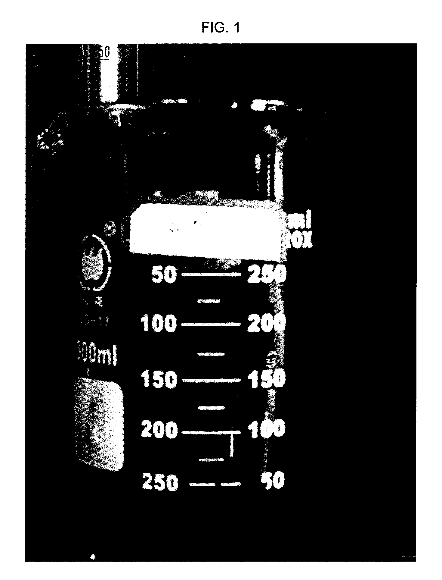
[0195]To tap water was added 20 kg / m3 of bentonite, 0.5 kg / m3 of soda ash (Na2CO3), 2 kg / m3 of polyanionic cellulose regular (PAC R), 1 kg / m3 of xanthan gum, 1 kg / m3 of polyanionic cellulose low viscosity (PAC LV) and 6 kg / m3 of drilling grade starch. This mixture was then mixed using a Hamilton Beach mixer for 20 minutes, at which point 80 kg / m3 of bitumen was added and further mixed for 20 minutes. The mixture was then left to sit at 11° C. for 16 hours. As can be seen in FIG. 1, this prior art drilling fluid composition comprising an anionic polymer is not able to encapsulate the bitumen.

example 2

Prior Art Composition Comprising Cationic Polymer

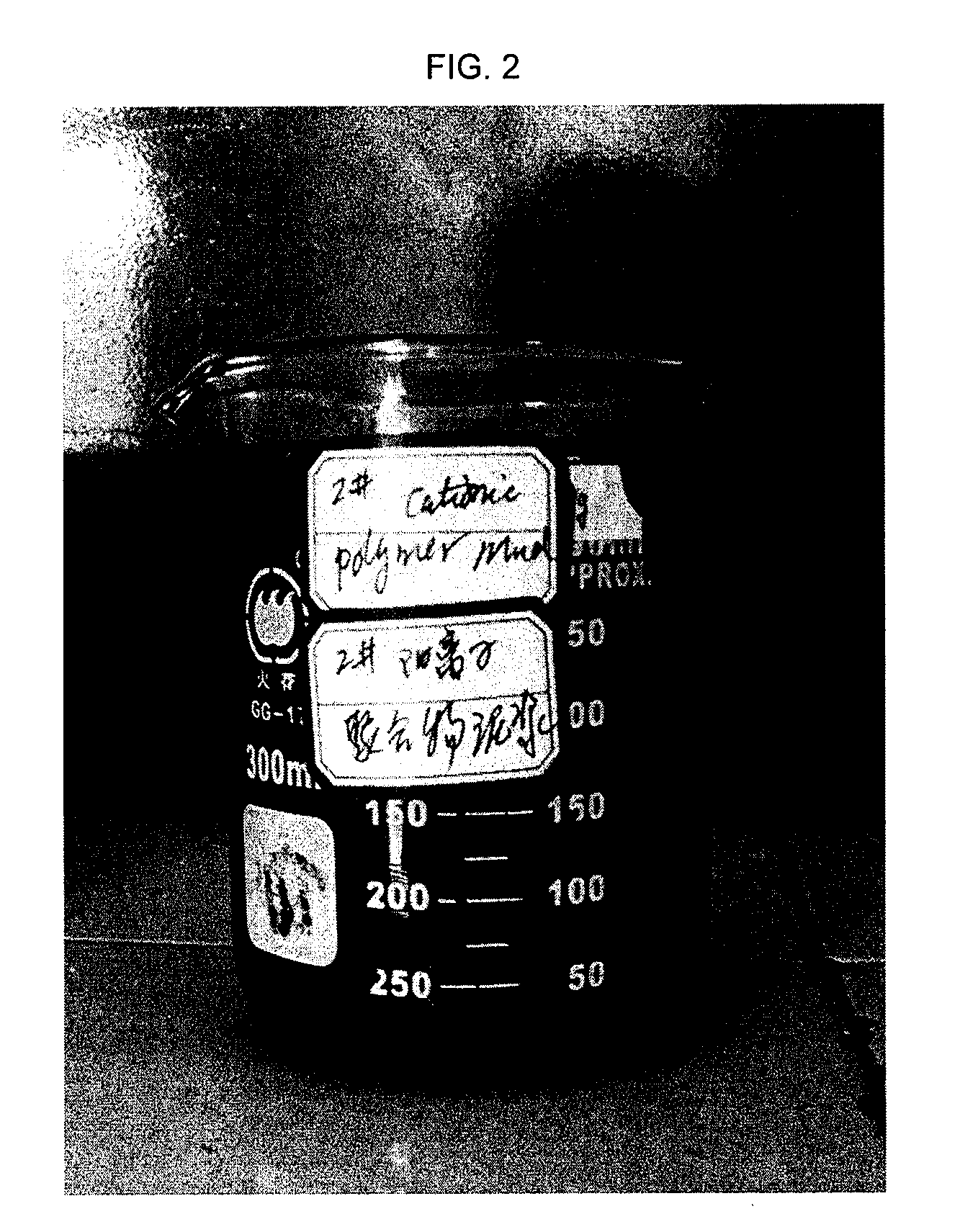
[0196]To tap water was added 20 kg / m3 of bentonite, 0.5 kg / m3 of soda ash (Na2CO3), 5 kg / m3 of cationic polymer (KT11-4: copolymer of acrylamide and 2-methacryloyloxyethyltri-methylammonium chloride), 1 kg / m3 of xanthan gum, 3 kg / m3 of polyanionic cellulose low viscosity (PAC LV) and 6 kg / m3 of drilling grade starch. This mixture was then mixed using a Hamilton Beach mixer for 20 minutes, at which point 80 kg / m3 of bitumen was added and further mixed for 20 minutes. The mixture was then left to sit at 11° C. for 16 hours. As can be seen in FIG. 2, this prior art drilling fluid composition comprising a cationic polymer is not able to encapsulate the bitumen.

example 3

Hydrophobic Polymer

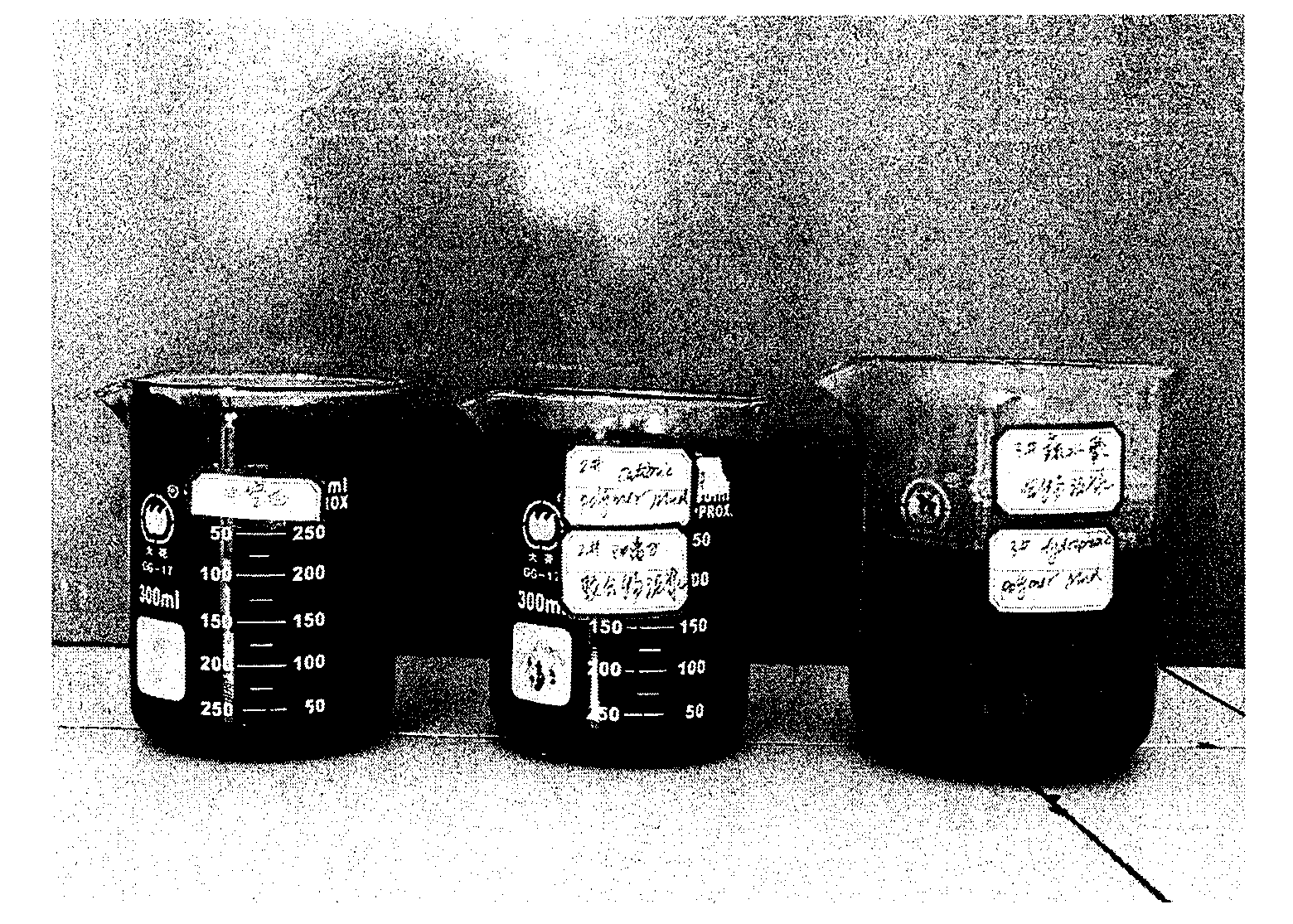
[0197]To tap water was added 20 kg / m3 of bentonite, 0.5 kg / m3 of soda ash (Na2CO3), 5 kg / m3 of hydrophobic polymer (BT 1217), 1 kg / m3 of xanthan gum, 3 kg / m3 of polyanionic cellulose low viscosity (PAC LV) and 6 kg / m3 of drilling grade starch. This mixture was then mixed using a Hamilton Beach mixer for 20 minutes, at which point 80 kg / m3 of bitumen was added and further mixed for 20 minutes. The mixture was then left to sit at 11° C. for 18 hours. As can be seen in FIG. 3, this drilling fluid composition comprising a hydrophobic polymer is able to encapsulate the bitumen as illustrated by the lighter colour of the mixture. Also, as seen in FIG. 4, the third beaker contains the hydrophobic polymer which results in the encapsulation of the bitumen, demonstrated by the lighter colour of the mixture in the third beaker compared to the first and second beakers.


PUM

PropertyMeasurementUnit
concentrationaaaaaaaaaa

Abstract

The present disclosure relates to drilling fluids for use in bitumen recovery from oil sands. In particular, the disclosure relates to a drilling fluid composition containing hydrophobically associating polymers which encapsulate the bitumen, and a method and use of the composition.

Description

FIELD OF THE DISCLOSURE[0001]The present disclosure relates to drilling fluid compositions for use in bitumen recovery from oil sands. The disclosure relates more particularly to a drilling fluid composition comprising hydrophobically associating polymers, and a method and use of said fluids to encapsulate bitumen.BACKGROUND OF THE DISCLOSURE[0002]In Canada, South America and China, there are very large oil sands deposits known as oil-rich bitumen sands. These oil sands consist of a mixture of crude bitumen (a semi-solid form of crude oil), silica sand, clay minerals, and water. The Canadian oil sand deposits cover over about 141,000 square kilometers and have about 28 billion cubic meters (174 billion barrels) of economically recoverable crude bitumen. There are two ways to recover the crude bitumen from these oil sand deposits. One way is mining and the other, is in-situ operations. In Canada, approximately 15.6 billion cubic meters (98 billion barrels) of crude bitumen deposit ca...

Claims


Application Information

Patent Timeline
Patent Type & Authority Applications(United States)
IPC IPC(8): C09K8/24
CPCC10G1/047
Inventor WU, AN MING
Owner MUD ENG
Learn More