Angled honeycomb seal between turbine rotors and turbine stators in a turbine engine

a technology of turbine engine and turbine rotor, which is applied in the direction of machines/engines, liquid fuel engines, mechanical equipment, etc., can solve the problems of leakage and the likelihood of failure, and achieve the effect of reducing the distance between the turbine stator and the turbine rotor

Inactive Publication Date: 2009-01-15
SIEMENS ENERGY INC
View PDF25 Cites 30 Cited by
  • Summary
  • Abstract
  • Description
  • Claims
  • Application Information

AI Technical Summary

Benefits of technology

[0003]This invention relates to a seal system for an intersection between two turbine components in a gas turbine engine. In at least one embodiment, the seal system may be configured to seal a gap at a gas turbine rim seal between a turbine stator and a turbine rotor. The seal system may

Problems solved by technology

In addition, turbine vanes and blades often contain cooling systems for prolonging the life of the vanes and blades and reducing the likelihood of fail

Method used


Image

  • Angled honeycomb seal between turbine rotors and turbine stators in a turbine engine
  • Angled honeycomb seal between turbine rotors and turbine stators in a turbine engine
  • Angled honeycomb seal between turbine rotors and turbine stators in a turbine engine

Examples


Embodiment Construction

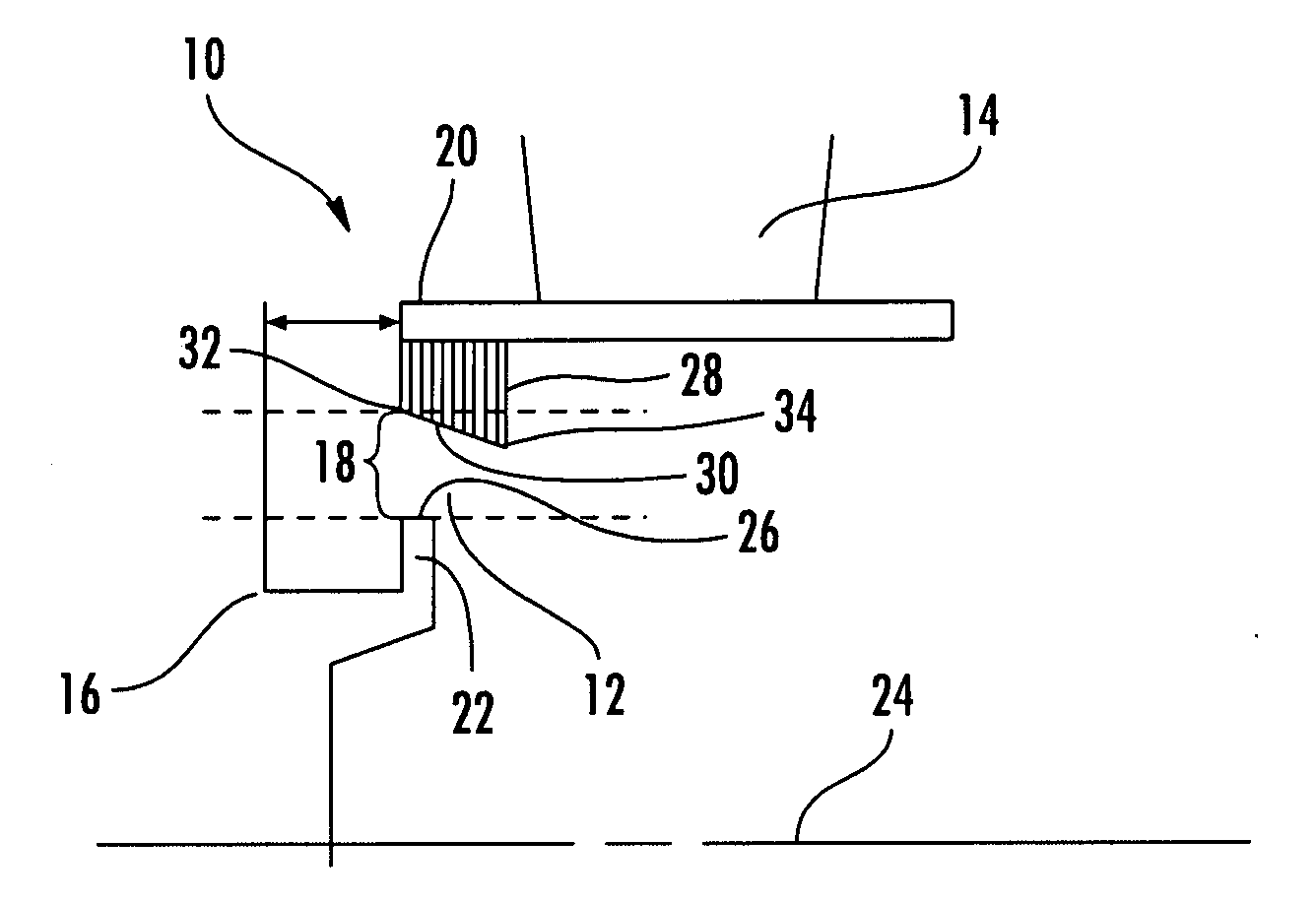
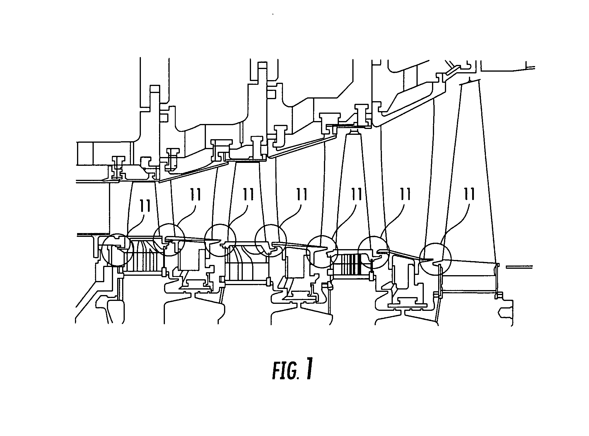
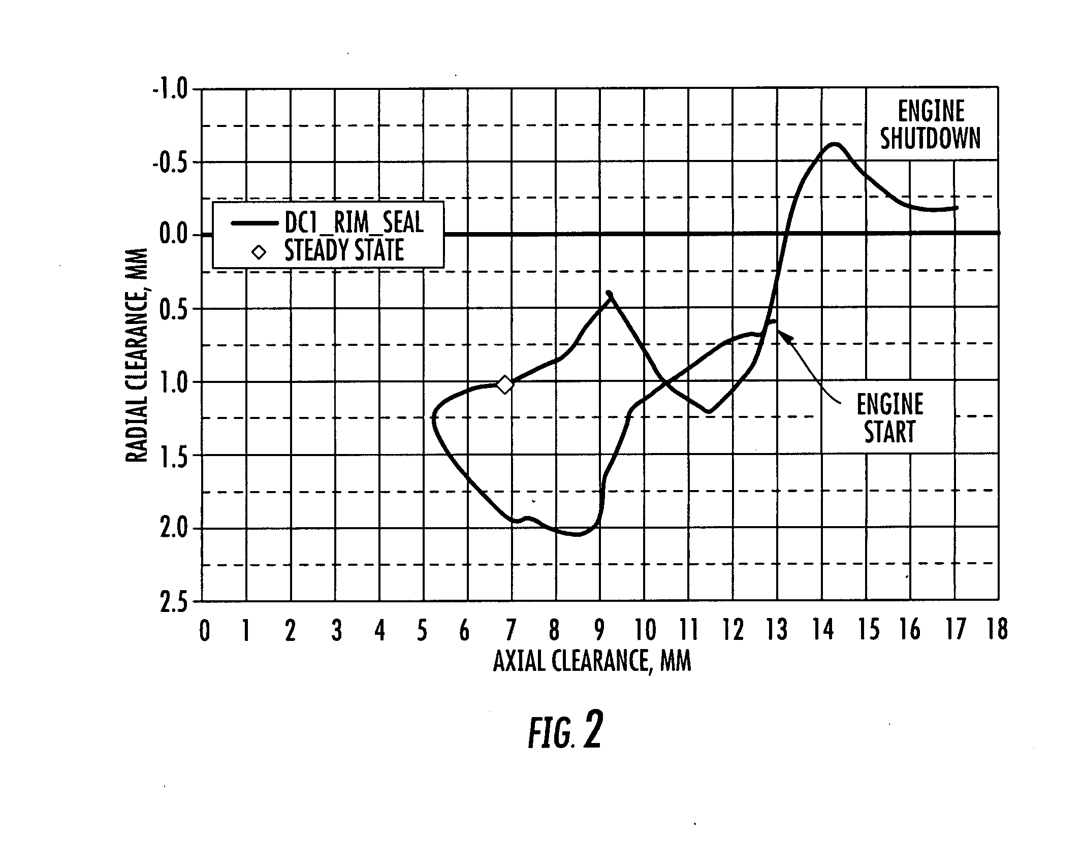
[0015]As shown in FIGS. 1-6, this invention is directed to a seal system 10 for an intersection 12 between two turbine components 14, 16 in a gas turbine engine. In at least one embodiment, the seal system 10 may be configured to seal a gap 18, as shown in FIG. 1, at a gas turbine rim seal 11 between a turbine stator 14 and a turbine rotor 16, as shown in FIGS. 3-6. The seal system 10 may be configured such that as the turbine engine heats up while moving through transient engine operation and approaching a steady state operating condition and the turbine rotor 16 undergoes axial movement, as shown in FIG. 2, the distance across the gap 18 between the turbine stator 14 and the turbine rotor 16 is reduced.

[0016]As shown in FIGS. 3-6, the seal system 10 may include a seal base 20 extending from the turbine stator 14. The seal system 10 may also include an arm 22 extending from the turbine rotor 16 and toward the seal base 20, but terminating short of the seal base 20 thereby creating ...


PUM


Abstract

A seal system for an intersection between a turbine stator and a turbine rotor to seal cooling fluids. The seal system may be formed from a seal base extending from the turbine stator, an arm extending radially outward from the turbine rotor and toward the seal base but terminating short of the seal base thereby creating a gap between the seal base and the arm. The seal system may include a honeycomb shaped seal attached to the seal base and extending radially inward from the seal base toward the arm. An outer sealing surface of the seal may be nonparallel with a longitudinal axis about which the turbine rotor rotates thereby enabling the distance of the gap to be reduced with axial movement of the turbine rotor.

Description

FIELD OF THE INVENTION[0001]This invention is directed generally to turbine engines, and more particularly to seal systems for the intersection between turbine stators and rotors to seal cooling systems.BACKGROUND[0002]Typically, gas turbine engines include a compressor for compressing air, a combustor for mixing the compressed air with fuel and igniting the mixture, and a turbine blade assembly for producing power. Combustors often operate at high temperatures that may exceed 2,500 degrees Fahrenheit. Typical turbine combustor configurations expose turbine vane and blade assemblies to these high temperatures. As a result, turbine vanes and blades must be made of materials capable of withstanding such high temperatures. In addition, turbine vanes and blades often contain cooling systems for prolonging the life of the vanes and blades and reducing the likelihood of failure as a result of excessive temperatures. Turbine engines typically include a plurality of rows of stationary turbi...

Claims


Application Information

Patent Timeline
IPC IPC(8): F01D11/08F04D29/08F16J15/447
CPCF01D11/001F01D11/04F01D11/08F16J15/444F01D11/127F01D11/22F01D11/122
Inventor PU, ZHENGXIANGYIN, YAN
Owner SIEMENS ENERGY INC
Why Eureka
Try Eureka