Input regulated DC to DC converter for power scavenging

a technology of input voltage, which is applied in the direction of electric variable regulation, process and machine control, instruments, etc., can solve the problems of excessive voltage drop across the input terminal, unfit dc to dc converters for some applications requiring voltage conversion, and unregulated voltage across the input terminal of available dc to dc converters

Active Publication Date: 2009-01-15
FISHER CONTROLS INT LLC
View PDF5 Cites 57 Cited by
  • Summary
  • Abstract
  • Description
  • Claims
  • Application Information

AI Technical Summary

Benefits of technology

[0010]A method of scavenging power in a current loop involves inserting a scavenging device in series with a power source and a power consuming device, regulating the voltage drop across the input terminals of the scavenging device, and providing power at the output terminals available from the controlled voltage drop and the loop current. In particular, voltage drop across the scavenging device is regulated by means of a feedback circuit generating an input voltage signal and a regulator circuit using the input voltage signal to control the timing of charging and discharging an inductor. The regulator circuit may be a conventional DC to DC converter or a circuit having several discrete components such as comparators.

Problems solved by technology

This property makes the available DC to DC converters unfit for some applications requiring voltage conversion.
Unfortunately, the available DC to DC converters do not regulate voltage across their input terminals.
In order to output constant voltage, these converters consume the necessary power at the input terminals which may sometimes cause an excessive voltage drop across the input terminals.
However, this limiting circuit would simply waste useful power.
On the other hand, a feedback circuit could be used to gate the scavenging circuit on and off or, in other words, “pulse” the operation the circuit, but this approach would generate low frequency noise which may interfere with signaling in the current loop.
Further, the converters known in the art do not provide an efficient means of harvesting additional power available at the input.
For example, a scavenger load consuming relatively little power will cause the scavenging device to draw this necessary amount of power at the input terminal regardless of the actual capability of the current loop.
Just like the power consumption at the output terminals may be excessive and may disturb the current loop, consuming too little power is undesirable because this approach fails to efficiently utilize the current loop.
Moreover, there may be instances when the supply current drops significantly and the scavenger load may not receive enough power.
Still further, the available DC to DC converters cannot control the rate of change of current flowing through a converter and thus do not provide a way of controlling AC impedance.
Because modulation requires a certain minimum impedance in order to work efficiently, modulating across a low impedance current loop wastes large amounts of electrical power.
Finally, the use of known DC to DC converters in scavenging devices in a variable current environment does not provide a desired level of operational safety.
In a fault condition, the capacitor may discharge the power back to the input terminals and thus create a safety hazard in the current loop.
In an explosive environment, the energy discharged by the storage device may trigger an explosion.
While the safety could be improved by placing several diodes in series, instead of one typically used in a converter, this approach would significantly degrade the operation of the circuit.
Moreover, a short circuit inside the DC to DC controller could also cause this problem and thus provide another path for the transfer of energy back to the input terminals.

Method used


Image

  • Input regulated DC to DC converter for power scavenging
  • Input regulated DC to DC converter for power scavenging
  • Input regulated DC to DC converter for power scavenging

Examples


Embodiment Construction

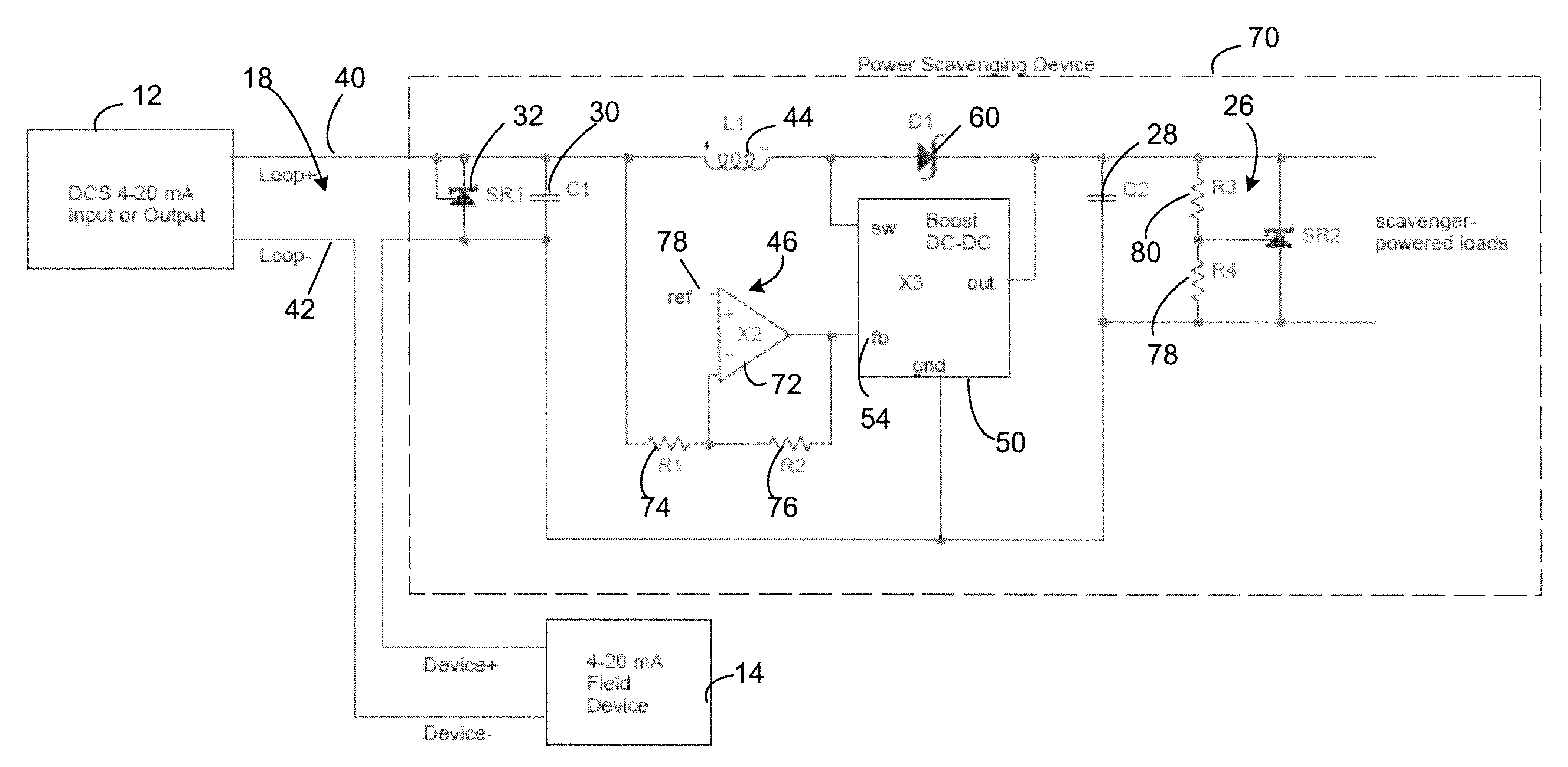
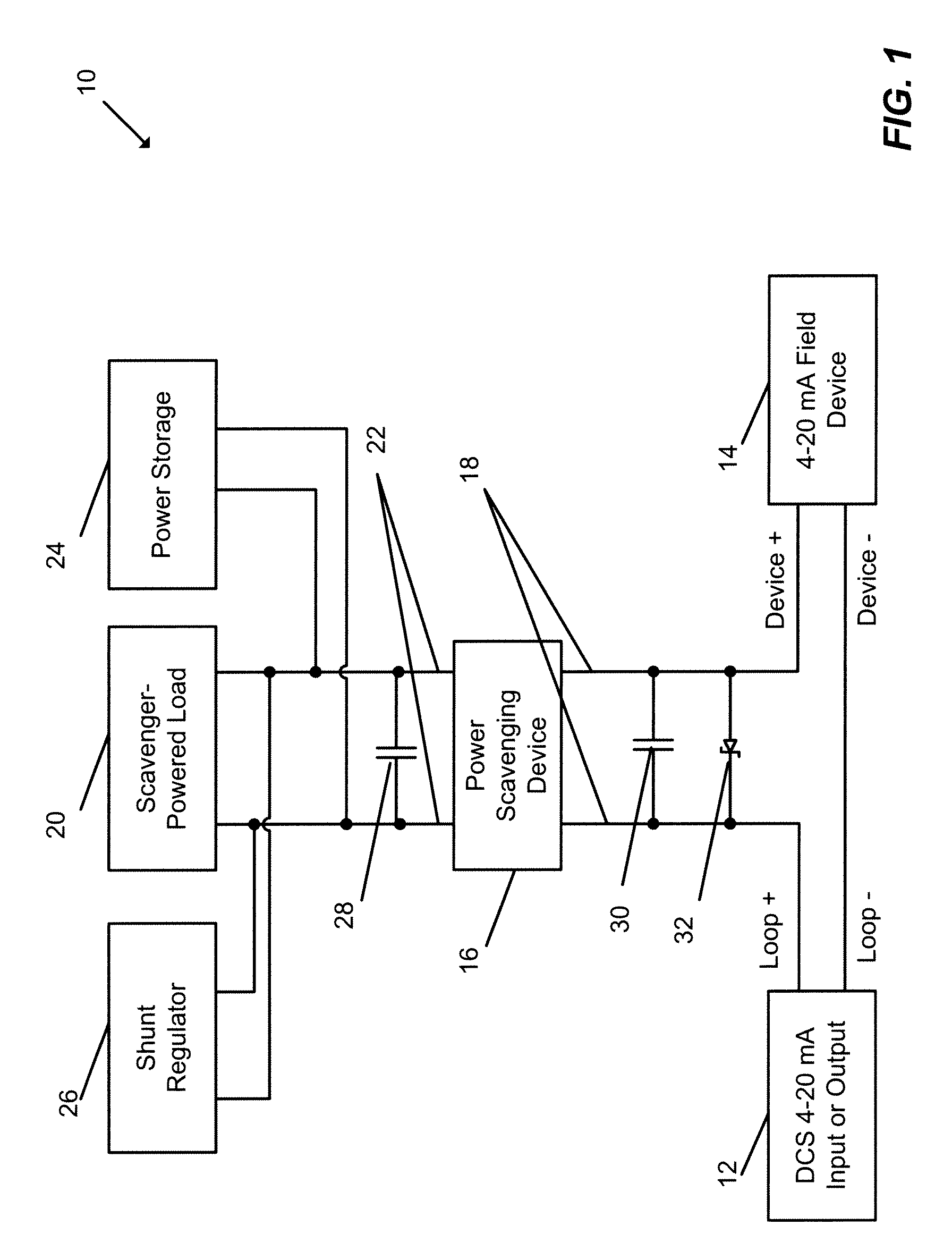
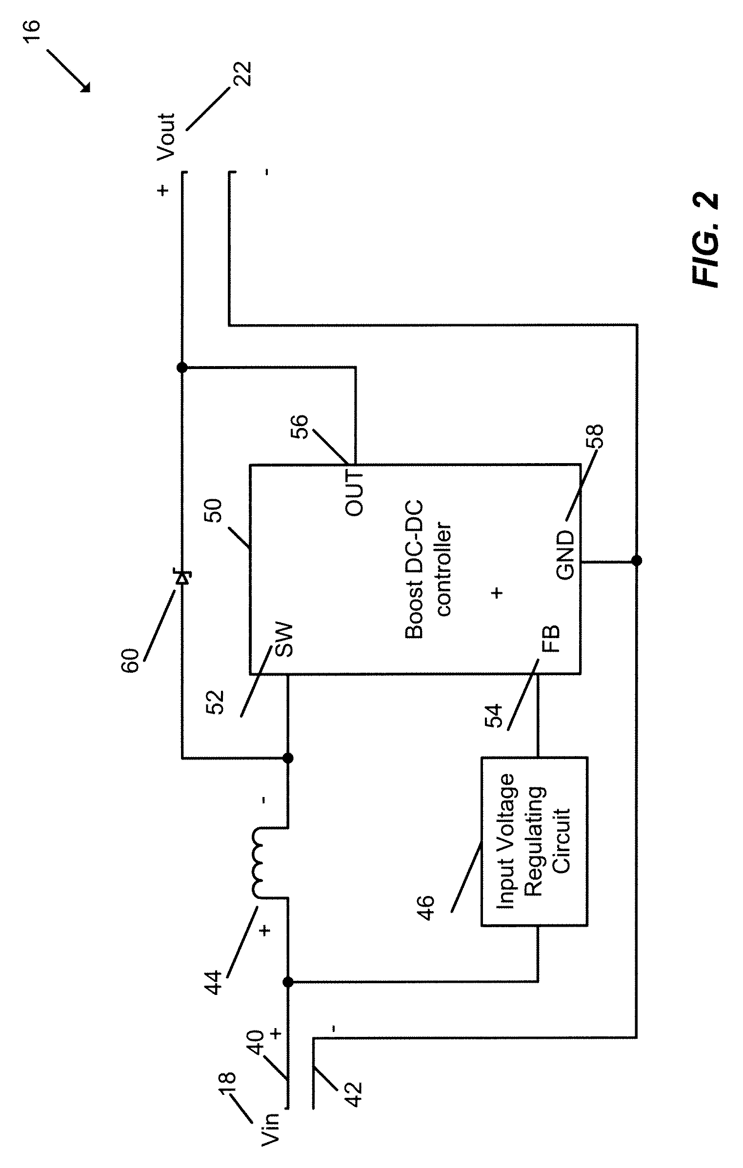
[0020]FIG. 1 is a schematic representation of a system in which an input-regulated power scavenging device may be used to efficiently harvest excess power from a current loop and direct the excess power to a load, a storage device, or both. As illustrated in FIG. 1, a current loop or circuit 10 includes a Distributed Control System (DCS) 12, a field device 14, and a power scavenging device 16 connected in series with the field device 14. These and other circuit elements illustrated in FIG. 1 are connected in a wired manner.

[0021]In operation, the DCS 12 and the field device 14 send and receive 4-20 mA analog signals in a manner unpredictable to the scavenging device 16 implemented as an input regulated DC to DC converter. In other words, from the perspective of the scavenging device 16, the current in the loop 10 may uncontrollably vary with time in the 4 to 20 mA range. The power scavenging device is connected to the loop 10 in series through a pair of input terminals 18, with one ...


PUM


Abstract

A method of scavenging power in a circuit having a power source generating electric current includes connecting a power scavenging device having an input terminal pair and an output terminal pair to the circuit via the input terminal pair, dynamically regulating a voltage drop across the input terminal pair of the power scavenging device, harvesting electrical energy available at the regulated voltage drop from the electric current flowing through the first input terminal pair of the power scavenging device, and providing the harvested electrical energy at the output terminal pair of the power scavenging device.

Description

CROSS-REFERENCE TO RELATED APPLICATIONS[0001]This application claims benefit of the following U.S. Provisional Application Ser. No. 60 / 944,454, entitled “Input Regulated DC to DC Converter for Power Scavenging” filed Jun. 15, 2007 (attorney docket no. 06005 / 561853P), the disclosure of which is hereby expressly incorporated herein by reference.FIELD OF THE INVENTION[0002]The present invention relates generally to voltage and power conversion circuits and, more particularly, to a method and apparatus for regulating input voltage of a DC to DC converter.DESCRIPTION OF THE RELATED ART[0003]DC to DC converters are used in a variety of applications to produce regulated voltage. Some converters, known as step-up or boost converters, generate higher voltage at the output terminals than is available at the input terminals. Conversely, step-down converters generate lower voltage at the output terminals. The DC to DC converters known in the art typically operate by controlling, through dedicat...

Claims


Application Information

Patent Timeline
Patent Type & Authority Applications(United States)
IPC IPC(8): G05F1/10
CPCH02M3/155H02J7/345H02M2001/0006H02M2001/0022H02M1/0022H02M1/0006
Inventor SEBERGER, STEPHEN G.WITTKOP, ADAM J.
Owner FISHER CONTROLS INT LLC
Why Eureka
Try Eureka