Eureka AIR delivers breakthrough ideas for toughest innovation challenges, trusted by R&D personnel around the world.

Phase Sensitive Fourier Domain Optical Coherence Tomography

Inactive Publication Date: 2009-01-15
ECOLE POLYTECHNIQUE FEDERALE DE LAUSANNE (EPFL)
View PDF2 Cites 67 Cited by
  • Summary
  • Abstract
  • Description
  • Claims
  • Application Information

AI Technical Summary

Benefits of technology

[0032]A further object of this invention is a high-speed phase-resolved FDOCT method without mechanically moving parts providing a high stability during signal acquisition.

Problems solved by technology

However, TDOCT has some important limitations.
First, in TDOCT, the image acquisition rate is mainly limited by the technical requirements for the depth scan.
This translates often into an increase of complexity for the scanning system with a decreasing reliability especially for OCT-systems with high acquisition speeds close or at video rates.
Second, the serial signal acquisition in TDOCT during an A-scan is not very efficient.
This limitation is particular important in opthalmology where the maximum power is limited due to safety reasons, particular in retina diagnosis.
Third, the serial scanning in TDOCT demands that the sample under investigation remains stationary during the whole tomographic image acquisition time, otherwise motion artefacts may severely degrade the image quality.
Initial attempts and implementations of FDOCT suffered from several unwanted signal contributions resulting from:1) Large DC-components on the array detector caused by non-interfering contributions from the sample and reference arm.
These contributions degraded the image quality of the first FDOCT instruments.
Nevertheless this method does not double the depth range.
However existing limitations within this prior art FDOCT exist and include:1) wavelength dependent phase shifts2) limited axial resolution due to wavelength dependant phase shifts3) reduced phase stability due to mechanical arm length changes4) limited image acquisition rate due to arm length changes based on arm length movements

Method used


Image

  • Phase Sensitive Fourier Domain Optical Coherence Tomography
  • Phase Sensitive Fourier Domain Optical Coherence Tomography
  • Phase Sensitive Fourier Domain Optical Coherence Tomography

Examples


first embodiment

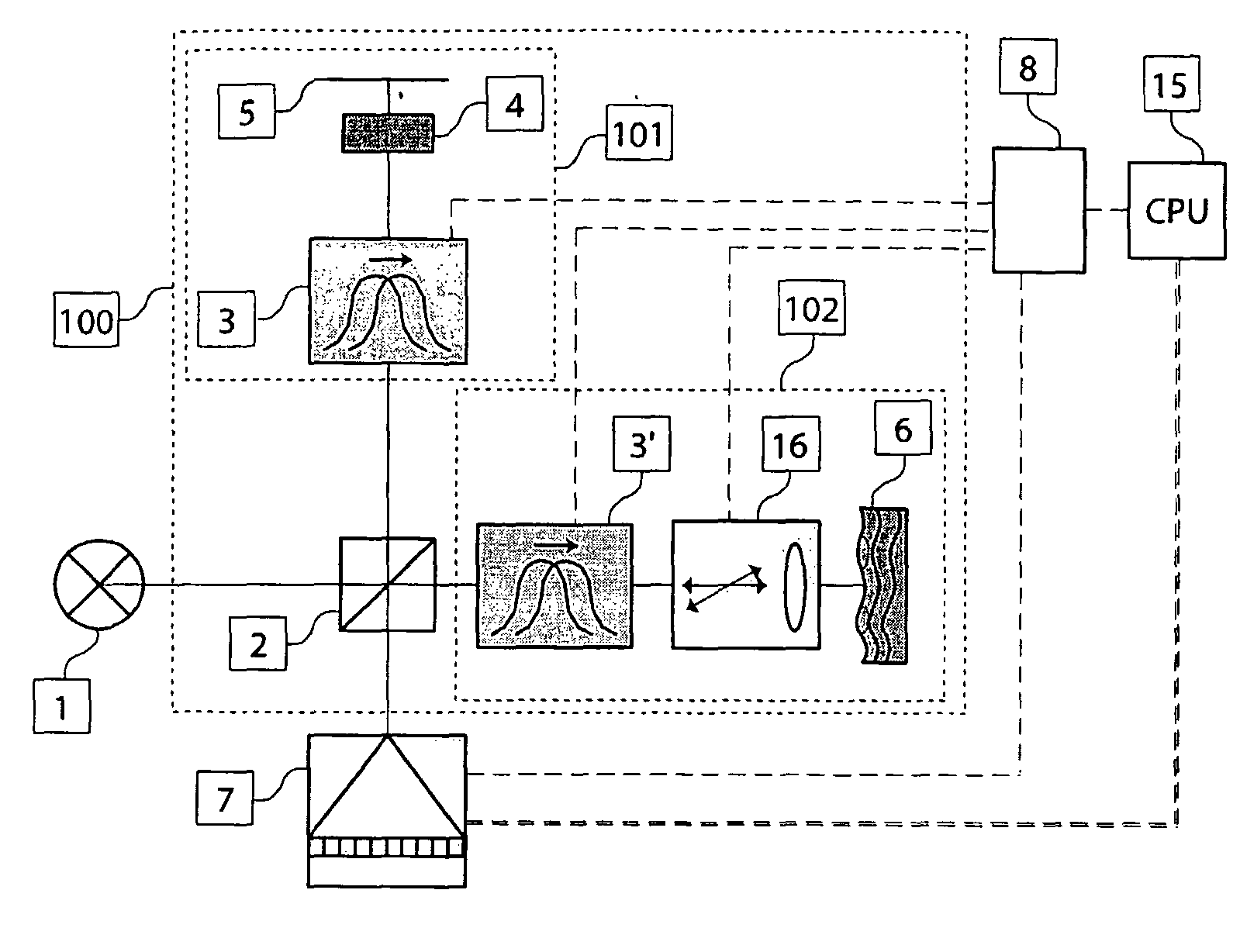
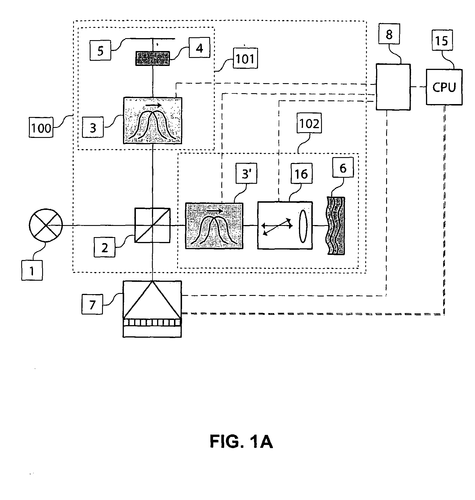
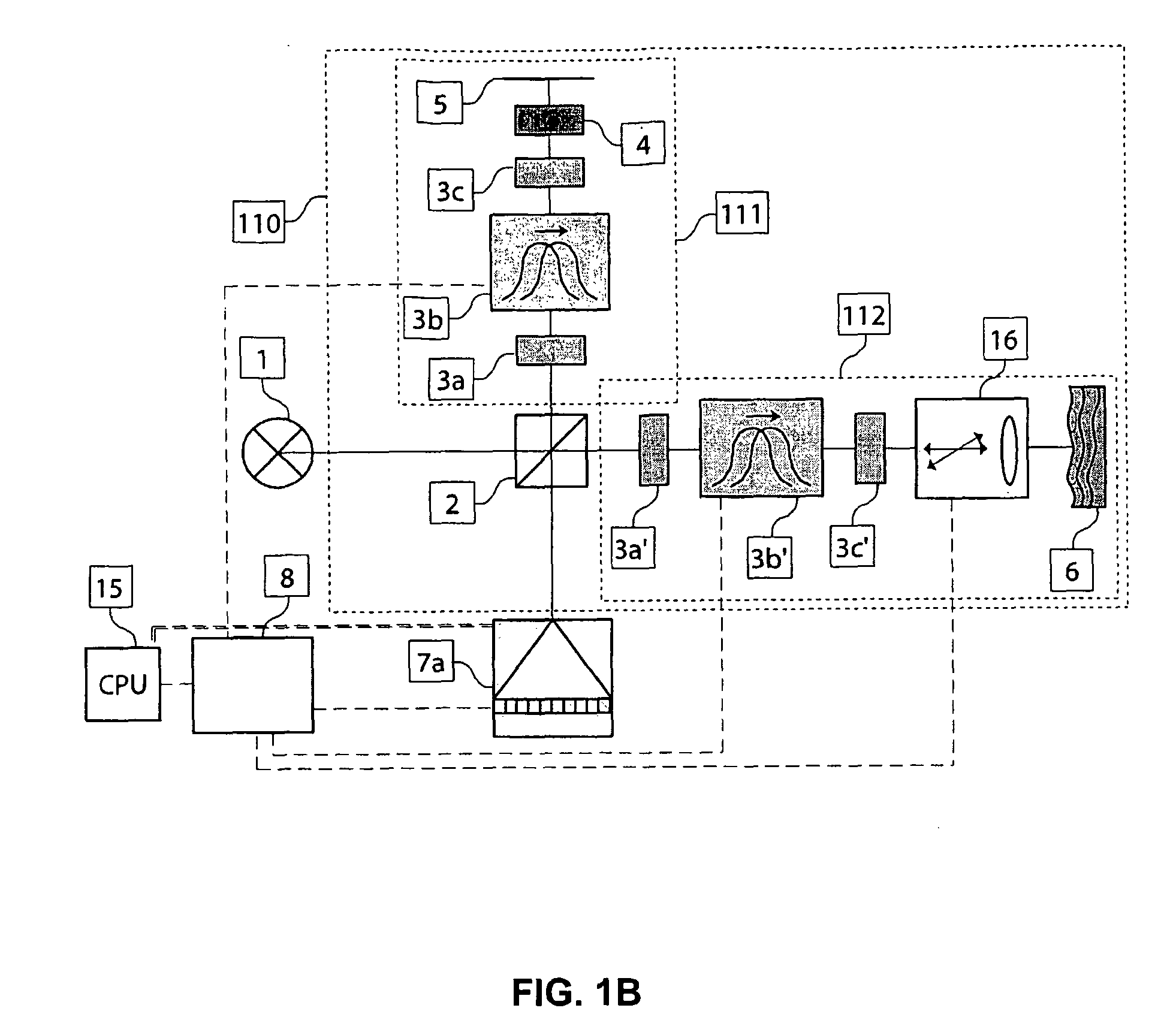
[0075]Referring to FIG. 1C, a second phase sensitive FDOCT system 1C in accordance with one possible embodiment of the present invention, is shown. The FDOCT system 1C of FIG. 1C corresponds to a fiberized version of a Michelson interferometer setup 120 illuminated by a partially coherent broadband source 1 in close resemblance to the first embodiment shown in FIG. 1B.

[0076]The light beam exiting from the source 1 is injected into a fiberized imaging Michelson interferometer setup 120. All or a part of these elements in this setup 120 are selected from the group of fiberized components.

[0077]As will be appreciated by those of ordinary skill in the art, there are several ways to realize the fiberized beam dividing and recombining device 11. This beam splitting component 11, which splits and redirects the light field into a reference 121 and a sample arm 122, can also be realized with so-called optical circulators, which may result in a setup with lower loss.

[0078]Frequency shifting m...

fourth embodiment

[0129]Referring to FIG. 2E, an eighth phase sensitive FDOCT system 2E in accordance with one possible embodiment of the present invention, is shown. The FDOCT system 2E of FIG. 2E corresponds to a fiberized version of a Mach-Zehnder like imaging interferometer setup 240 illuminated by a partially coherent broadband source 1 in close resemblance to the fourth embodiment shown in FIG. 2A.

[0130]The light beam exiting from the source 1 is injected into a fiberized Mach-Zehnder interferometer setup 240. All or a part of the elements in this setup 240 are selected from the group of fiberized components.

[0131]The fiberized beam splitting device 11a splits the light field into a reference 241 and sample arm 242. Both interferometer arms 241 and 242 contain frequency shifting means 3b and 3b′. The reference arm 241 may optionally include a dispersion compensation mean 4, which can be optionally realized by bulk optic elements. The back reflecting element 5 can be realized via a bulk optic re...

eighth embodiment

[0136]Referring to FIG. 2F, a ninth phase sensitive FDOCT system 2F in accordance with one possible embodiment of the present invention, is shown. The FDOCT system 2F of FIG. 2F corresponds to a fiberized and polarization sensitive version of a Mach-Zehnder like imaging interferometer setup 250 illuminated by a partially coherent broadband source 1 in close resemblance to the eighth embodiment shown in FIG. 2E.

[0137]The light beam exiting from the source 1 is injected into a fiberized Mach-Zehnder interferometer setup 250. All or a part of the elements in this setup 250 are selected from the group of fiberized and preferably polarization maintaining components.

[0138]The fiberized beam splitting device 11a splits the light field into a reference 251 and sample arm 252. Both interferometer arms 251 and 252 are equipped with frequency shifting means 3b and 3b′. The reference 251 and sample arm 252 include optionally a dispersion compensation mean 4, which can be optionally realized by ...


PUM


Abstract

Optical Coherence Tomography (OCT) is an imaging technique with high axial resolution in the micro-meter-scale range combined with a high sensitivity allowing for example to probe weakly back-scattering structures beneath the surface of biological tissues up to several millimeters. A major improvement of this conventional technique represents Fourier Domain OCT with a further decrease in image acquisition time and additional sensitivity. The apparatus including appropriate signal processing reconstructs the depth profile from the spectrally resolved light signal generated by a broadband source and an interferometric imaging system. By frequency shifting the light fields with frequency shifting means in the reference and sample arm a phase resolved signal at high speed can be registered. Therefore the reference arm does not rely on arm length changes or delays. The beating signal generated in this way shows high phase stability. The phase of this beating signal is not wavelength dependent, as the frequency shift applied is the same for all wavelengths. Moreover this results in an additional suppression of unwanted auto-correlated distortion as well as an extended depth range.

Description

FIELD OF THE INVENTION[0001]The invention relates to imaging systems and more particularly to tomographic and interferometric imaging systems with phase resolution.BACKGROUND OF THE RELATED ART[0002]Optical Coherence Tomography (OCT) is a non-contact imaging modality based on the coherence properties of light. This optical tomography developed due to its steady progress over the last two decades from the initial proposal into a diagnostic tool for medicine as well as an imaging modality for biological applications.[0003]OCT is an interferometric imaging technique that allows for high-resolution, cross-sectional imaging of biological tissue. In the standard time-domain (TD) implementation of OCT, a low-coherent light from a broadband source is divided into the reference path and into the sample path. The interference pattern as a result of the superposition of back-reflected light from the sample as well as the reference path contains information about the scattering amplitude as wel...

Claims


Application Information

Patent Timeline
IPC IPC(8): G01B9/02
CPCA61B5/0066A61B5/0073A61B5/7257G01B9/02003G01B2290/45G01B9/02091G01B9/02069G01B2290/70G01B9/02044
Inventor LEITGEB, RAINERBACHMANN, ADRIANLASSER, THEO
Owner ECOLE POLYTECHNIQUE FEDERALE DE LAUSANNE (EPFL)
Why Eureka
Eureka Blog
Learn More