

Image processing method, apparatus, recording medium, and image pickup apparatus
a pickup apparatus and image processing technology, applied in the field of image noise reduction process, can solve the problems of complicated control and processing time between two regions, and achieve the effect of improving the skin tone of human subjects and maintaining background image quality
- Summary
- Abstract
- Description
- Claims
- Application Information
AI Technical Summary
Benefits of technology
Problems solved by technology
Method used
Image

Examples
first embodiment
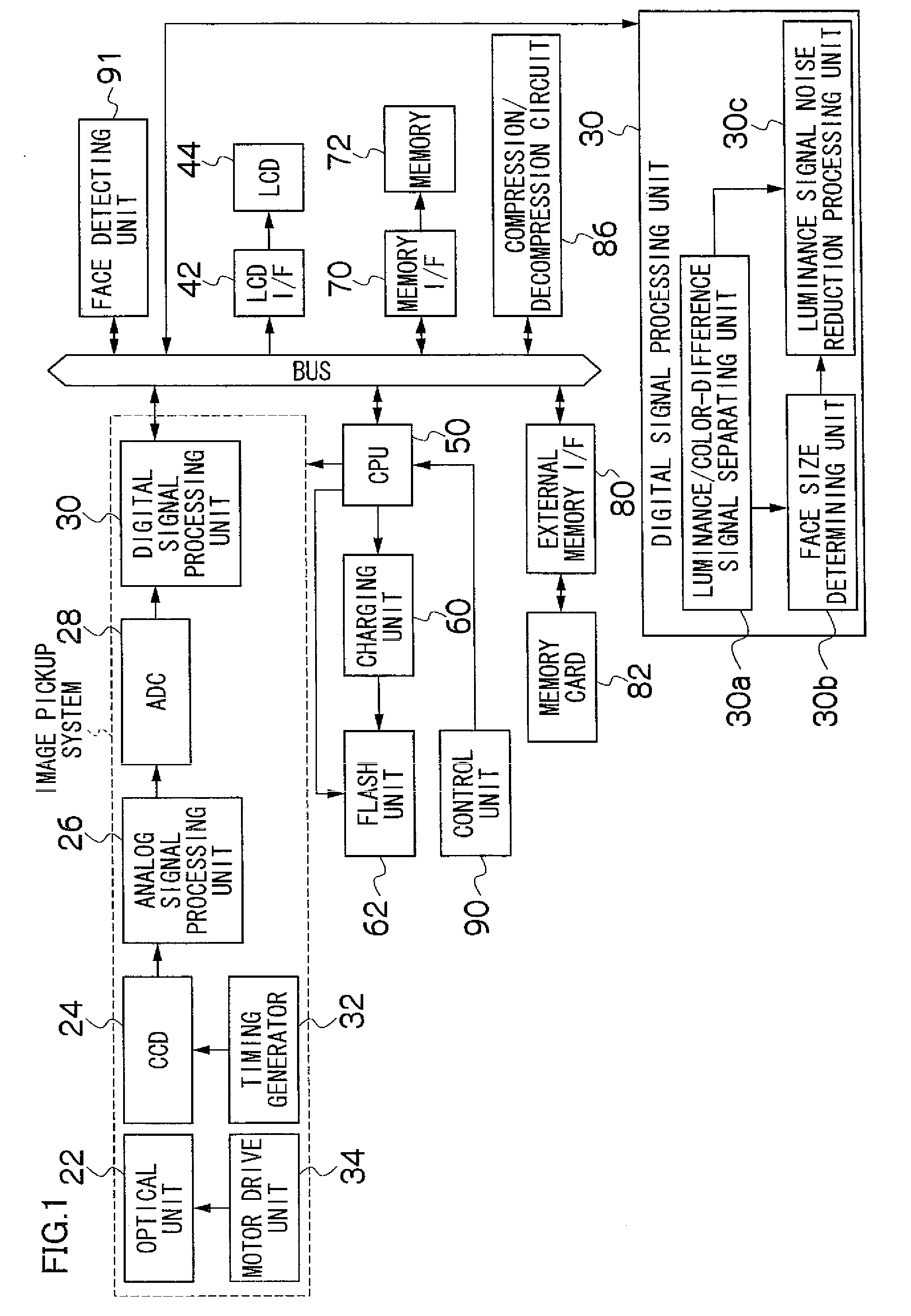
[0082]FIG. 1 shows an electrical configuration of a digital camera 10. As shown in FIG. 1, the digital camera 10 comprises: an optical unit 22 which includes a lens; a CCD 24 disposed behind an optical axis of the lens; an analog signal processing unit 26 which includes a correlated double sampling circuit (hereinafter referred to as a “CDS”); an analog / digital converter (hereinafter referred to as an “ADC”) 28 which converts an inputted analog signal into digital data; and an digital signal processing unit 30 which incorporates a line buffer of predetermined capacity, directly stores inputted digital image data in a predetermined area of a memory 72 described later, and performs various types of image processing on the digital image data. An output terminal of the CCD 24 is connected to an input terminal of the analog signal processing unit 26, an output terminal of the analog signal processing unit 26 is connected to an input terminal of the ADC 28, and an output terminal of the A...
second embodiment
[0125]FIG. 7 shows a detailed configuration of the digital signal processing unit 30 in the digital camera 10 according to a second embodiment. The digital signal processing unit 30 according to the second embodiment includes a color-difference signal noise reduction processing unit 30d instead of the luminance signal noise reduction processing unit 30c, compared with the configuration in the first embodiment. The same components as those in the other embodiments are designated by the same reference numerals as the corresponding components in the other embodiments.
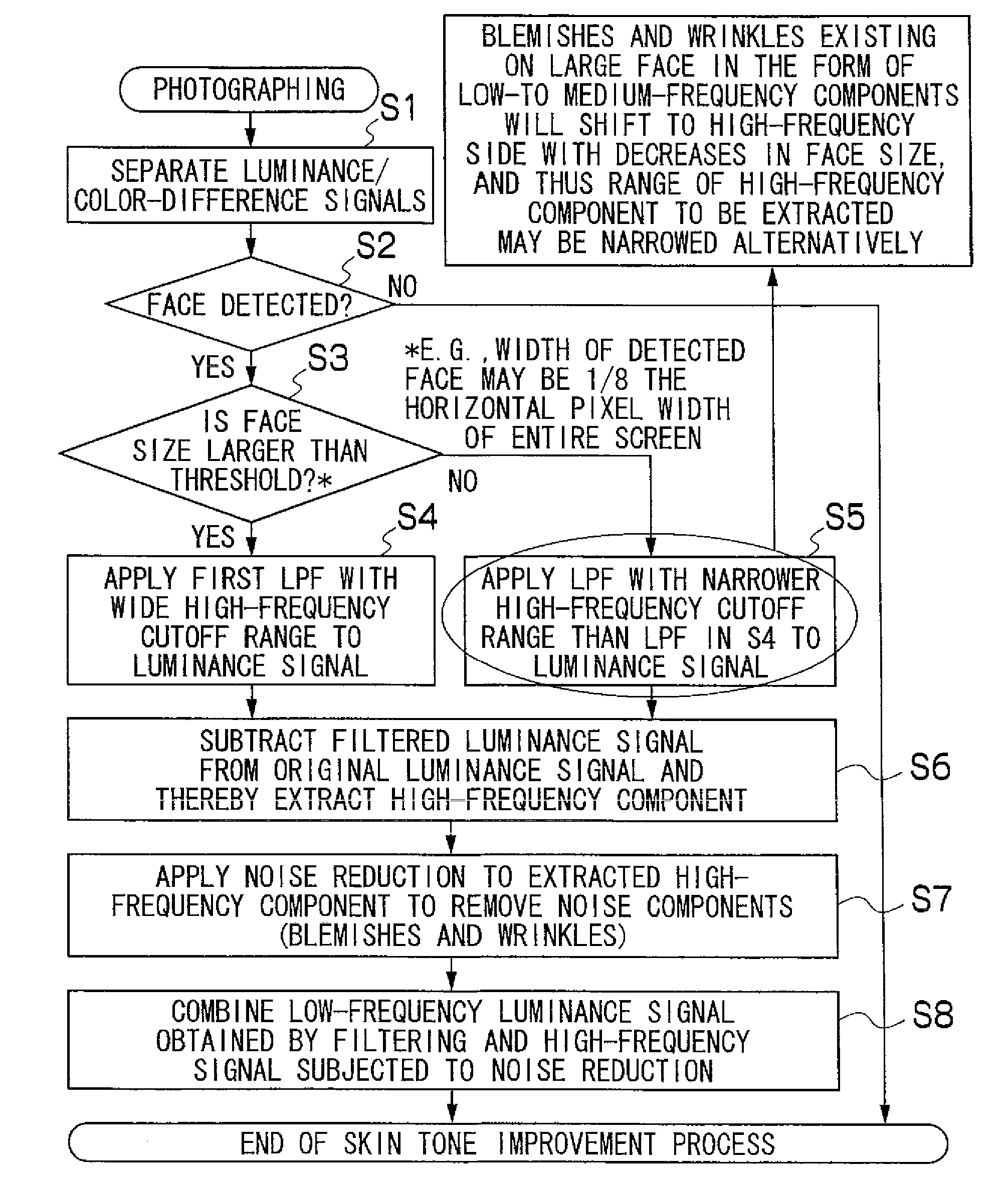
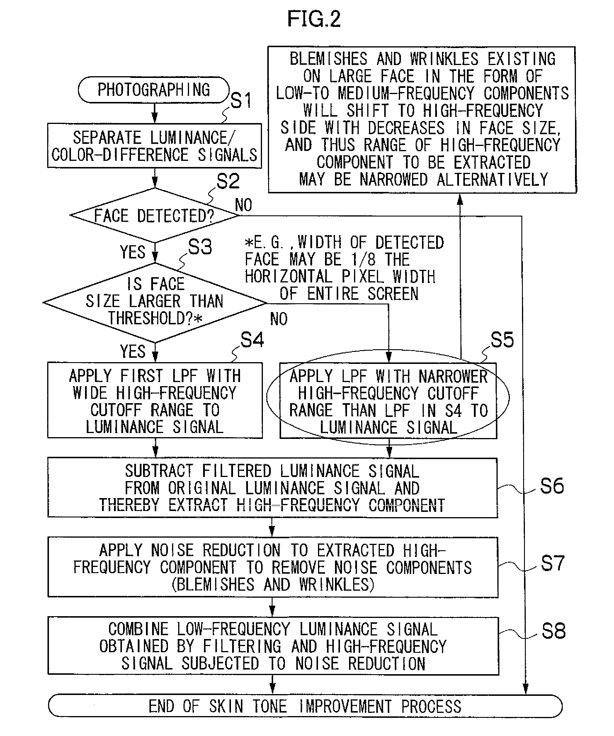
[0126]FIG. 8 illustrates a flow of a skin tone improvement process performed by the digital camera 10 according to the second embodiment.
[0127]In S11, the luminance / color-difference signal separating unit 30a performs Y / C processing to convert R, G, and B data of an original photographic image outputted from the ADC 28 into the luminance signal Y and color-difference signals Cr and Cb (the color-difference signals will be ...
third embodiment
[0144]FIG. 11 shows a detailed configuration of the digital signal processing unit 30 in the digital camera 10 according to a third embodiment. The digital signal processing unit 30 includes a luminance signal frequency splitting unit 30e and frequency band-specific luminance signal noise reduction processing unit 30f as well as the luminance / color-difference signal separating unit 30a and the face size determining unit 30b. The same components as those in the other embodiments are designated by the same reference numerals as the corresponding components in the other embodiments.
[0145]FIG. 12 illustrates a flow of a skin tone improvement process performed by the digital camera 10 according to the third embodiment.
[0146]S21 is the same as S1.
[0147]In S22, the luminance signal Y is divided into a plurality of frequency bands (e.g., three bands: high, medium, and low).
[0148]In S23, the frequency band-specific luminance signal noise reduction processing unit 30f extracts from the lumina...
PUM
 Abstract
Description
Claims
Application Information