Material for organic electroluminescence device and organic electroluminescence device utilizing the same
Active Publication Date: 2009-01-15
IDEMITSU KOSAN CO LTD
View PDF6 Cites 1149 Cited by
Summary
Abstract
Description
Claims
Application Information
AI Technical Summary
This helps you quickly interpret patents by identifying the three key elements:
Problems solved by technology
Method used
Benefits of technology
Benefits of technology
[0022]The present invention has been made to overcome the above problems and has an object of providing a material for organic EL devices which realizes an EL device exhibiting a high efficiency of light emission, causing little pixel defects, exhibiting a high heat resistance and having a long lifetime.
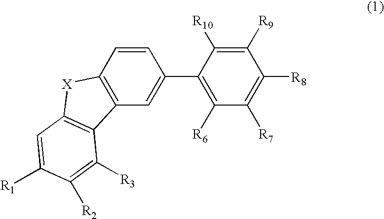
[0023]As a result of extensive research in view of achieving the above object, the inventors have found that a compound represented by the following formula 1, which has a dibenzothiophene or dibenzofuran structure having at its 2-position substituted with an aromatic hydrocarbon group, creates a excited triplet state having a sufficient energy level enough to prevent the emitting efficiency of a blue phospholescent complex from being reduced. It has been further found that the compound realizes a highly efficient and highly heat-resistant organic EL device causing little pixel defects and having a long lifetime. The present invention is based on these findings.
[0031]The organic EL device made using the material for organic EL devices of the present invention is free from pixel defects, highly efficient, highly heat resistant and durable for a long period of time.
Problems solved by technology
However, there is nothing about their advantage in the device performance as compared with a host material having a carbazole structure.
Image
Click on the blue label to locate the original text in one second.
Reading with bidirectional positioning of images and text.
Examples
synthesis example 1
Synthesis of Compound No. 4
[0134](1) Synthesis of 2,8-dibromodibenzofuran
[0135]A three-necked flask was charged with dibenzofuran (100.91 g, 600 mmol) and 300 ml of AcOH and the contents were heated to 40° C. Then, a solution of Br2 (191.8 g, 1200 mmol) / AcOH 300 ml was added dropwise. After stirring for 9 h at 40° C., the mixture was refluxed for 6 h. After the reaction, the reaction production solution was cooled to room temperature and added with 600 ml of water. The precipitate collected by filtration was dissolved in toluene. The resultant solution was dried over anhydrousmagnesiumsulfate, filtrated and concentrated. The obtained solid product was recrystallized from hexane five times to obtain the titled compound (62.83 g, 32% yield).
[0137]A three-necked flask was charged with 2,8-dibromodibenzofuran (39.12 g, 120 mmol), carbazole (20.07 g, 120 mmol), K3P...
synthesis example 2
Synthesis of Compound No. 9
[0142]
[0143]A three-necked flask was charged with compound 2a (6.3 mmol, 2.85 g), compound 1b (6 mmol, 2.47 g), Na2CO3 2M aq. (6 ml), Pd[PPh3]4 (0.3 mmol, 0.35 g), DME (12 ml), and toluene (6 ml), and the mixture was refluxed for 9 h. After the reaction, the reaction product solution was cooled to room temperature and extracted with CH2Cl2 using a separatory funnel. The extract was dried over anhydrousmagnesiumsulfate, filtrated and concentrated. The obtained solid product was purified by a column chromatography (hexane:toluene=6:4). The purified product was further washed with ethanol and vacuum-dried to obtain a white solid. The above operations were all performed in an argonatmosphere (2.12 g, 48% yield).
[0146]A three-necked flask was charged with compound 3a (7.35 mmol, 2.12 g), compound 1b (7 mmol, 2.89 g), Na2CO3 2M aq. (7 ml), Pd[PPh3]4 (0.35 mmol, 0.40 g), DME (14 ml), and toluene (7 ml), and the mixture was refluxed for 9 h. After the reaction, the reaction product solution was cooled to room temperature and extracted with CH2Cl2 using a separatory funnel. The extract was dried over anhydrousmagnesiumsulfate, filtrated and concentrated. The obtained solid product was purified by a column chromatography (hexane:toluene=6:4). The purified product was further washed with ethanol and vacuum-dried to obtain a white solid. The above operations were all performed in an argonatmosphere (2.55 g, 63% yield).
PUM
Property
Measurement
Unit
Wavelength
aaaaa
aaaaa
Energy gap
aaaaa
aaaaa
Fraction
aaaaa
aaaaa
Abstract
A material for organic electroluminescence devices of the invention which is for use in combination with at least one phosphorescent metal complex has a specific heterocyclic structure. The material for organic electroluminescence devices is used as a host material or a hole transporting material. An organic electroluminescence device having an anode, a cathode and an organic thin film layer having one or more layers which is interposed between the anode and cathode, in which at least one layer of the organic thin film layer contains the material for organic electroluminescence devices, has a high emitting efficiency, causes little pixel defects, is excellent in heat resistance, and shows a long lifetime.
Description
BACKGROUND OF THE INVENTION[0001]1. Field of the Invention[0002]The present invention relates to materials for organic electroluminescence devices and organic electroluminescence devices using the materials and, more particularly to materials for organic electroluminescence devices which realize electroluminescence devices exhibiting a high emitting efficiency, causing little pixel defects, exhibiting a high heat resistance and having a long lifetime.[0003]2. Description of the Prior Art[0004]An organic electroluminescence device (organic ELdevice) is a spontaneous emission device which utilizes the phenomenon of fluorescence which occurs by the energy of recombination between holes injected from an anode and electrons injected from a cathode by application of electric field. As the structure of organic EL devices, a two-layered structure having a hole transporting (injecting) layer and an electron transporting / light emitting layer and a three-layered structure having a hole transpo...
Claims
Application Information
Patent Timeline
Application Date:The date an application was filed.
Publication Date:The date a patent or application was officially published.
First Publication Date:The earliest publication date of a patent with the same application number.
Issue Date:Publication date of the patent grant document.
PCT Entry Date:The Entry date of PCT National Phase.
Estimated Expiry Date:The statutory expiry date of a patent right according to the Patent Law, and it is the longest term of protection that the patent right can achieve without the termination of the patent right due to other reasons(Term extension factor has been taken into account ).
Invalid Date:Actual expiry date is based on effective date or publication date of legal transaction data of invalid patent.

