Organic light-emitting apparatus and method of producing the same

Inactive Publication Date: 2009-01-22
CANON KK
View PDF3 Cites 25 Cited by
  • Summary
  • Abstract
  • Description
  • Claims
  • Application Information

AI Technical Summary

Benefits of technology

[0012]It is, therefore, an object of the present invention to provide an organic light-emitting apparatus in which a crack or the like produced when removing a passivation layer on an e

Problems solved by technology

The characteristics of an organic light-emitting device which constitutes an organic light-emitting apparatus are liable to be degraded due to moisture, oxygen or the like.
The presence of even a small amount of moisture can result in peeling between an organic compound layer and an electrode layer, which becomes a cause of a dark spot.
However, there has been a problem that deflection of a substrate constituting the organic light-emitting device or deflection of the area mask creates a gap between the substrate and the area mask to form a passivation layer also on the external connection terminal.
However, when the passivation layer is peeled to be removed using a masking tape, photoetching, laser irradiation, or blasting, a minute crack, peeling, or the like is produced in a cross section of the passivation layer.
These develop

Method used


Image

  • Organic light-emitting apparatus and method of producing the same
  • Organic light-emitting apparatus and method of producing the same
  • Organic light-emitting apparatus and method of producing the same

Examples


embodiment 1

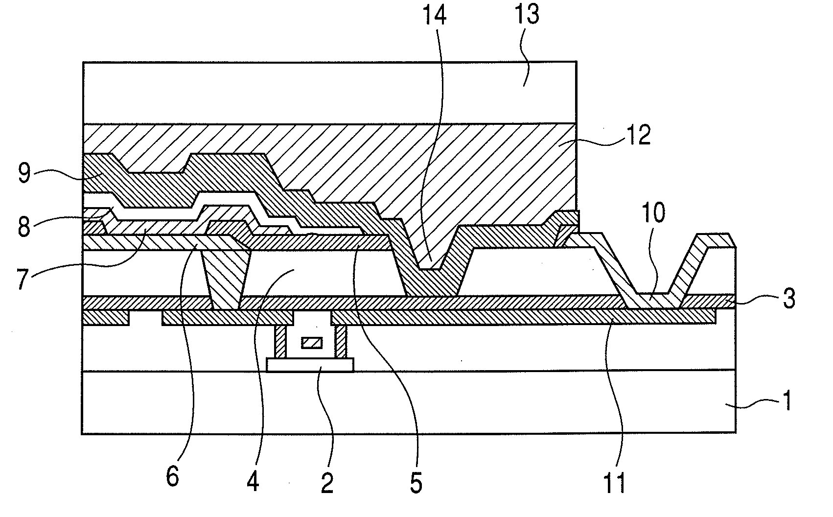
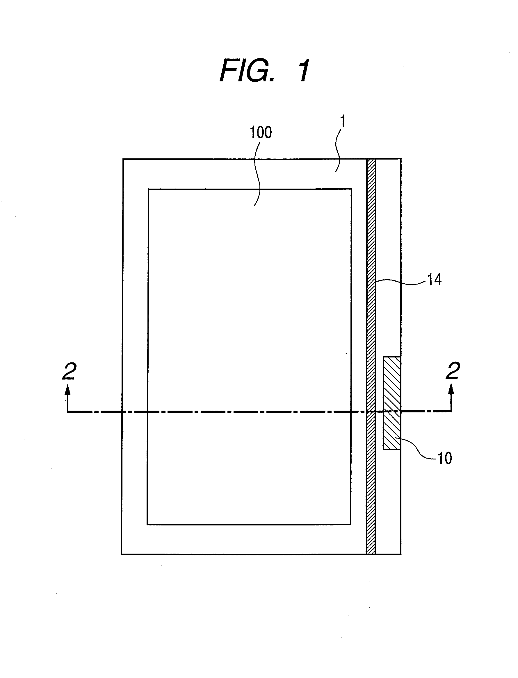
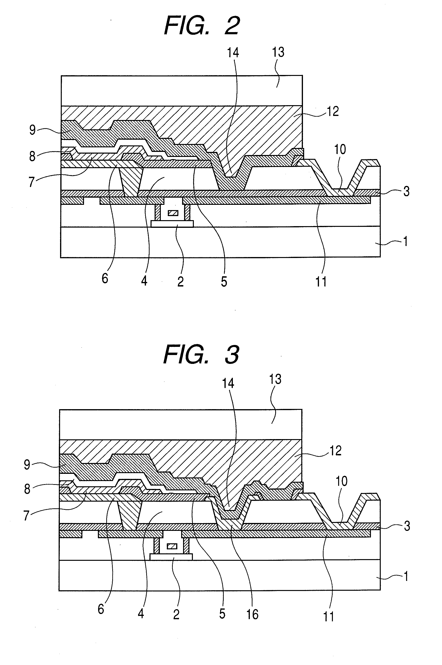
[0026]Embodiment 1 of the present invention is described with reference to FIGS. 1 and 2. FIG. 2 is a schematic cross-sectional view taken along line 2-2 of FIG. 1.

[0027]First, a method of producing an organic light-emitting apparatus is described, and then the organic light-emitting apparatus is described.

[0028]The method of producing an organic light-emitting apparatus is suitably implemented as a method of producing an organic light-emitting apparatus including at least a substrate 1, an organic planarization layer 4 for planarizing unevenness of the substrate 1, organic light-emitting devices, and a passivation layer 9 which covers the above-mentioned components.

[0029]Thin-film transistors 2 for driving respective organic light-emitting devices were formed on the substrate 1. The substrate 1 may be either transparent or opaque, and may be an insulating substrate formed of a synthetic resin or the like, or alternatively, may be a conductive substrate or a semiconductor substrate ...

embodiment 2

[0047]While, in Embodiment 1 described above, the passivation layer 9 was formed directly on the discontinuous portion 14, as illustrated in FIG. 3, an inorganic layer 16 may be formed in the discontinuous portion 14 and the passivation layer 9 may be formed on the inorganic layer 16.

[0048]More specifically, when, for example, the upper electrode 8 was formed, a metal oxide conductive film of ITO, IZO, or the like which had the same composition as that of the upper electrode 8 was formed also in the discontinuous portion 14. By adopting such a configuration, the contact area between the side wall and its vicinity of the discontinuous portion 14 and the passivation layer 9 can be increased, so that the passivation layer 9 can be more closely contacted. In addition, because the adhesion between a metal oxide conductor which is a metal compound and the passivation layer is high, and because the coefficient of thermal expansion of the metal oxide conductor is far closer to that of the p...

embodiment 3

[0050]While, in Embodiments 1 and 2 above, the discontinuous portion 14 was formed in a line so as to separate the region including the light-emitting area 100 and the region including the external connection terminal 10, as illustrated in FIG. 4, the discontinuous portion 14 may be formed so as to surround the region including the external connection terminal 10. In this case, the area of the region including the external connection terminal 10 can be made minimum and waste produced when peeling the passivation layer 9 can be reduced. Further, because the development of cracking can be further suppressed, the sealing performance can be improved.


PUM


Abstract

Provided is an organic light-emitting apparatus in which a crack or the like produced when removing a passivation layer on an external connection terminal is prevented from developing with the elapse of time and the moisture resistance of a light-emitting area is not impaired. The organic light-emitting apparatus includes a substrate; an organic planarization layer for planarizing unevenness of the substrate; an organic light-emitting device including a lower electrode, an organic compound layer, and an upper electrode; and a passivation layer for covering the organic light-emitting device, in which the organic planarization layer has formed therein a recessed or protruding discontinuous portion for dividing a region including a light-emitting area and a region including an external connection terminal, and the discontinuous portion is covered with the passivation layer.

Description

BACKGROUND OF THE INVENTION[0001]1. Field of the Invention[0002]The present invention relates to an organic light-emitting apparatus used in a flat panel display or the like and a method of producing the same.[0003]1. Description of the Related Art[0004]In recent years, attention has been attracted to an organic light-emitting apparatus, which is a self-emission type device, as a flat panel display. The characteristics of an organic light-emitting device which constitutes an organic light-emitting apparatus are liable to be degraded due to moisture, oxygen or the like. The presence of even a small amount of moisture can result in peeling between an organic compound layer and an electrode layer, which becomes a cause of a dark spot. Therefore, such an organic light-emitting device is covered with an etching glass cover, its periphery is sealed with a sealing agent, and a desiccant is placed inside thereof such that moisture which intrudes through sealed surfaces is absorbed with the ...

Claims


Application Information

Patent Timeline
IPC IPC(8): H01J1/63B05D5/12
CPCH01L27/3258H01L51/5253H01L51/5237H01L27/3276H10K59/124H10K59/131H10K50/844
Inventor AOTA, YUKITO
Owner CANON KK
Why Eureka
Try Eureka