Unlock instant, AI-driven research and patent intelligence for your innovation.

Motor driver

a motor and driver technology, applied in the direction of motor/generator/converter stopper, dynamo-electric gear control, motor/generator/converter stopper, etc., can solve the problems of low drive efficiency of the motor and inability to highly efficiently drive the motor, and achieve the effect of easy assembly and quick construction

Inactive Publication Date: 2009-01-22
PANASONIC CORP
View PDF5 Cites 1 Cited by
  • Summary
  • Abstract
  • Description
  • Claims
  • Application Information

AI Technical Summary

Benefits of technology

[0022]When the motor driver of the invention is built in, or integrated with a motor, which includes a moving body and three-phase coils, it is possible to readily construct a high-efficiency driving system, which is easy to assemble into host equipment and includes a sinewave drive motor.

Problems solved by technology

However, the conventional motor driver described above involves a problem that it is not possible to highly efficiently drive motor 130.
Consequently, as shown in FIG. 6, the conventional motor driver involves a problem that it is not possible to make, for example, induced voltage Eu and drive current Iu in agreement with each other, and so the motor is lowered in drive efficiency.

Method used


Image

  • Motor driver
  • Motor driver
  • Motor driver

Examples


Embodiment Construction

[0029]An embodiment of the invention will be described below with reference to the drawings.

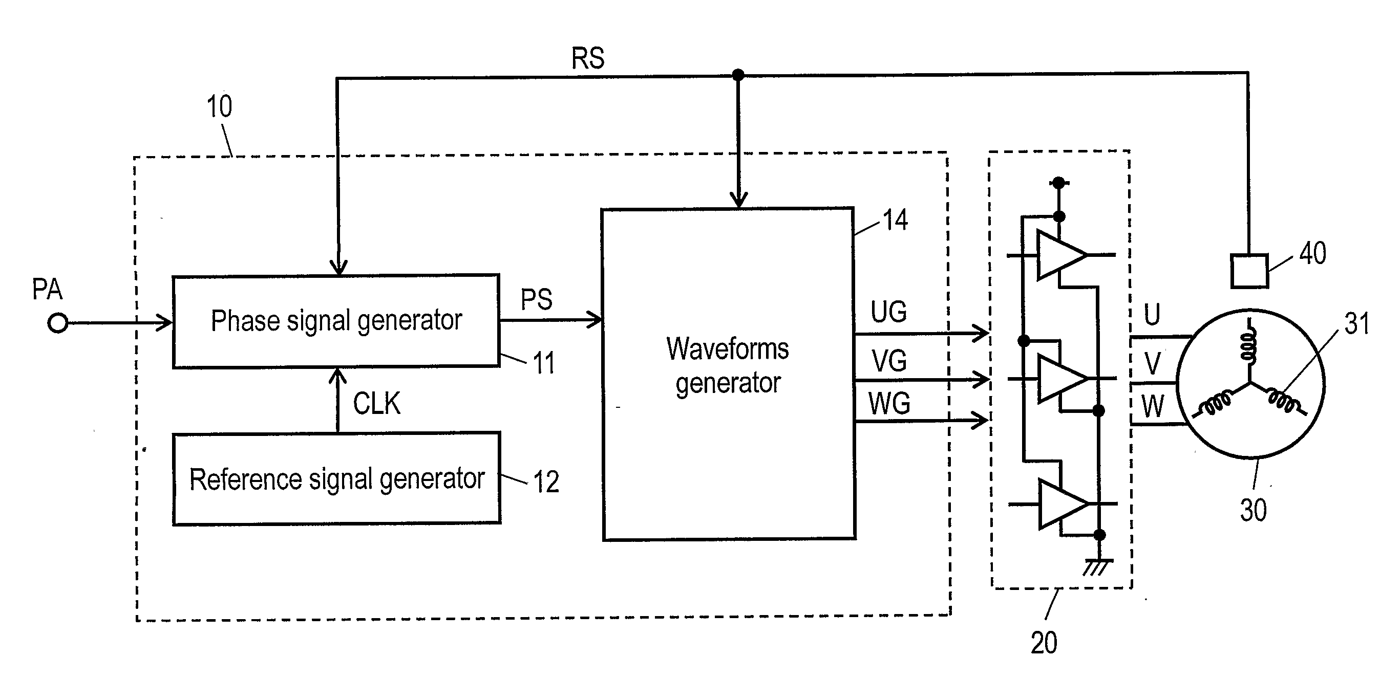
[0030]FIG. 1 is a circuit structure diagram of a motor driver according to an embodiment of the invention and FIG. 2 is a view illustrating an operation of the motor driver shown in FIG. 1. FIG. 3 is a view showing measurement of phase, in which a motor mounted as a fan motor on an air-conditioning equipment becomes highest in efficiency every drive speed and FIG. 4 is a view showing phase of drive voltage and drive speed of the motor driver according to the invention.

[0031]In FIG. 1, motor 30 includes a moving body (not shown) and three-phase coil 31. Drive voltage and drive current are supplied to coil 31 through a plurality of switching elements provided on energizing unit 20 from a dc power source (not shown).

[0032]The motor driver includes controller 10, which includes phase signal generator 11, reference signal generator 12, and waveforms generator 14, energizing unit 20, and speed-posi...


PUM


Abstract

A motor driver according to the invention comprises an energizing unit (20), which supplies drive voltage and drive current to a motor (30) including a moving body and three-phase coils (31), a speed-position detector (40), which detects drive speed of the motor and a position of the moving body to output, as a speed position signal RS, which includes drive-speed information and position information, a reference signal generator (12), which outputs a reference signal CLK for the drive speed, a phase signal generator (11), which uses a speed-position signal RS, a reference signal CLK, and a set signal PA indicative of an optional value to output a phase signal PS indicative of phase of the drive voltage supplied to the coil (31), and a waveforms generator (14), which uses the position information and a phase signal PS to output a control signal to the energizing unit (20). Phase of drive voltage supplied to the coil (31) is regulated so as to be proportional to the drive speed, and degree of the proportion can be set by the set signal PA.

Description

TECHNICAL FIELD[0001]The invention relates to a motor driver suited to driving of a brushless DC motor, etc. used in, for example, air-conditioning equipment, water heaters, on which a fan motor for burning is mounted, air cleaners, and information-processing equipment, such as copying machines, printers, etc. In particular, the invention relates to a motor driver for driving of a motor in a sinewave driving system capable of considerably reducing torque ripple, vibration, and noise at the time of motor driving.BACKGROUND ART[0002]Brushless DC motors (referred below to as motor) are in many cases used in various driving motors used in electrical equipment such as air-conditioning equipment, etc. while merits thereof, such as long life, high reliability, and easiness in speed control are made the most of.[0003]Conventionally, a rectangular-wave driving system, in which drive voltage supplied to a coil has a rectangular-wave shaped drive waveform, has been widely adopted as a motor dr...

Claims


Application Information

Patent Timeline
IPC IPC(8): H02P6/06
CPCH02P6/145H02P6/06H02P6/153
Inventor SUGIURA, KENJIYASOHARA, MASAHIRO
Owner PANASONIC CORP