Motor Drive Control System and Method for Controlling the Same

a control system and motor technology, applied in the direction of engine-driven generators, motor/generator/converter stoppers, electric devices, etc., can solve the problems of increasing the size of the drive circuit, increasing the noise, and deteriorating the control response, so as to achieve simple configuration without incurring deterioration of control performance and generating audible nois

Active Publication Date: 2009-01-22
DENSO CORP
View PDF6 Cites 47 Cited by
  • Summary
  • Abstract
  • Description
  • Claims
  • Application Information

AI Technical Summary

Benefits of technology

[0036]Accordingly, a chief advantage of the present invention is that, regarding the motor drive control configured to include the converter configured to be able to step up the output voltage of the DC power supply, the temperature increase due to heat generation of each switching device forming a part of the electric converter (inverter) when the motor is locked can be suppressed with a simple configuration without incurring deterioration of control performance and generation of audible noise.

Problems solved by technology

While the configuration disclosed in Patent Document 1 can reduce heat generation of the switching device when the motor is locked, the decreased carrier frequency deteriorates the control response and increases the noise because the switching frequency decreases to the audio frequency range.
Further, the configuration disclosed in Patent Document 2 has the problem that the size of the drive circuit as well as the cost are increased since the drive circuit used only when the motor is locked has to be additionally provided in parallel with the normally used drive circuit.

Method used


Image

  • Motor Drive Control System and Method for Controlling the Same
  • Motor Drive Control System and Method for Controlling the Same
  • Motor Drive Control System and Method for Controlling the Same

Examples


first embodiment

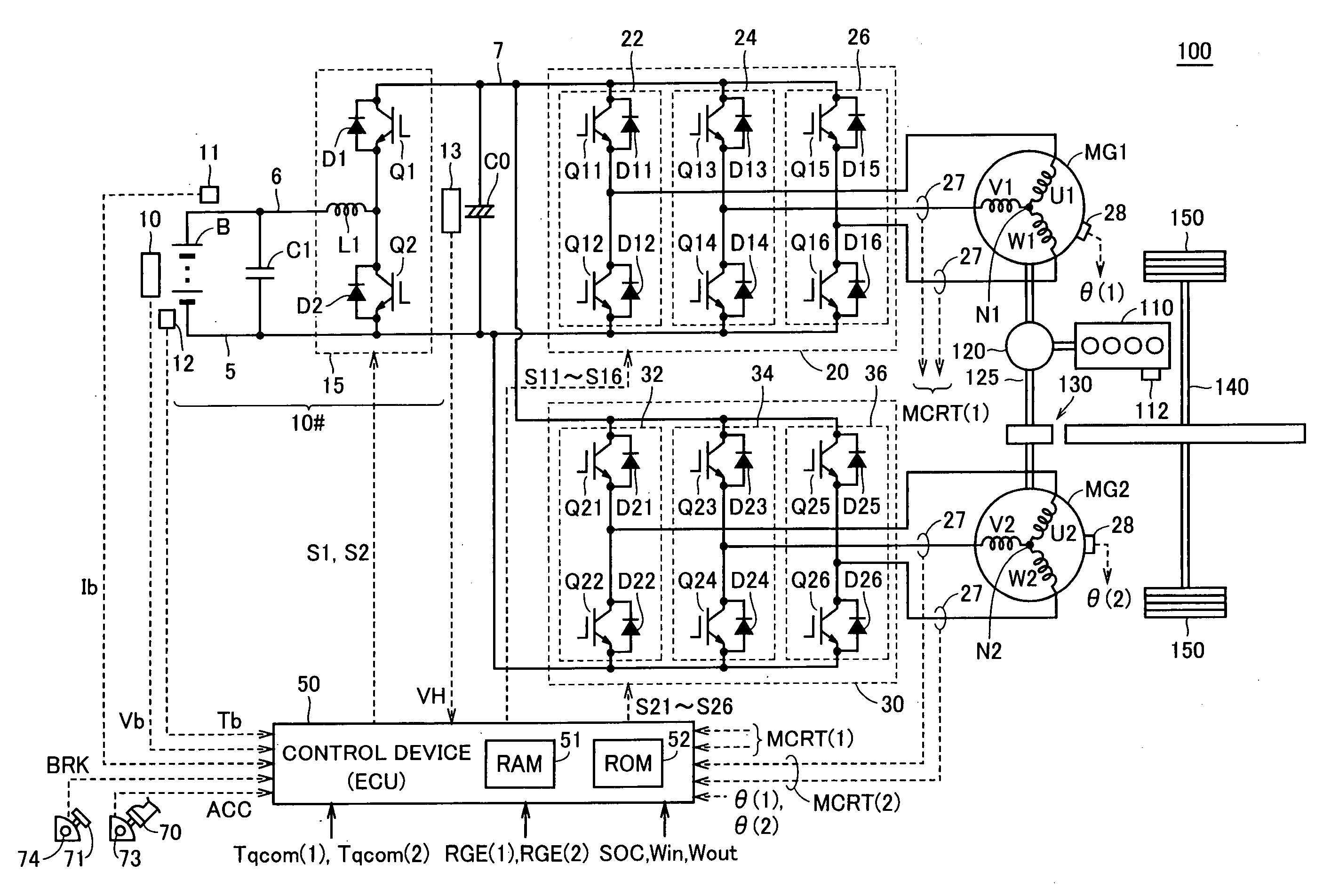
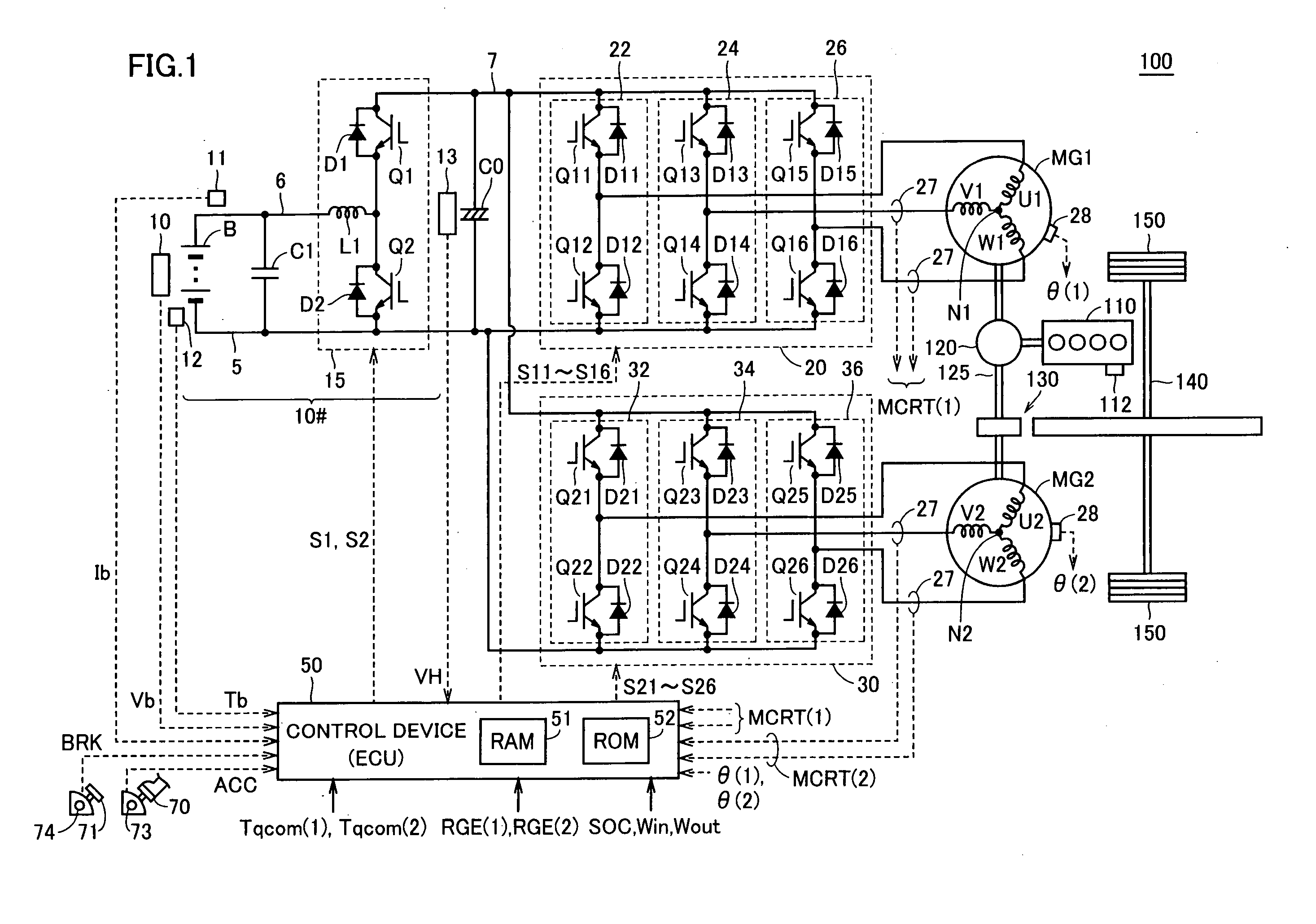
[0051]FIG. 1 is a block diagram illustrating a configuration of a hybrid vehicle 100 shown as an example of the configuration where a motor drive control system according to an embodiment of the present invention is mounted.

[0052]Referring to FIG. 1, hybrid vehicle 100 includes an engine 110, a power split device 120, motor generators MG1, MG2, a reduction gear 130, a driveshaft 140, and wheels (drive wheels) 150. Hybrid vehicle 100 further includes a DC voltage generating unit 10#, a smoothing capacitor C0, inverters 20, 30, and a control device 50, for driving and controlling motor generators MG1, MG2.

[0053]Engine 110 is formed of such an internal combustion engine as gasoline engine or diesel engine. Engine 110 is provided with a coolant temperature sensor 112 detecting the temperature of a coolant. The output of coolant temperature sensor 112 is sent to control device 50.

[0054]Power split device 120 is configured to be capable of splitting the motive energy generated by engine 1...

second embodiment

[0109]According to the first embodiment, the increase in temperature of the switching device when the locked state occurs is made gentle so that it is ensured that the locked electric motor (motor generator MG2) can continuously output a requested torque for a longer period of time (namely the period of time for which the locked state can be continued).

[0110]However, in the locked state where a relatively high torque output is required while the vehicle is driving uphill for example, if the electric power is supplied only from the running-purpose battery B (DC power supply), the remaining charge of the running-purpose battery B will suddenly decrease. In this respect, the period of time for which the locked state can be continued could be restricted. Therefore, according to a second embodiment, a description will be given of a control structure for ensuring a certain amount of electric power generated by the electric generator even in the locked state and ensuring the period of time...

third embodiment

[0126]In the hybrid vehicle, the case could occur where the locked state of motor generator MG2 occurs while the engine is stopped and further a request to start engine 110 is given. For example, the above-described case occurs when the remaining charge of running-purpose battery B decreases while the locked state continues and thus a request to charge is given, or when the extent to which the accelerator pedal is depressed by the driver (accelerator pedal depression) increases. In a third embodiment, a description will be given of how the above-describe case should be addressed.

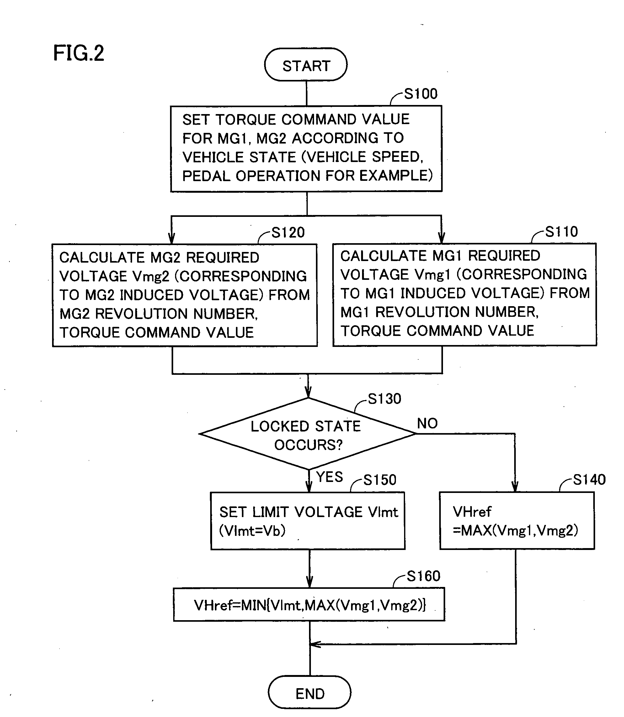
[0127]FIG. 9 is a flowchart illustrating control of hybrid vehicle 100 according to the third embodiment of the present invention. Regarding the program that follows the flowchart shown in FIG. 9 as well, it is supposed that the program is stored in ROM 52 in control device 50 and executed in predetermined cycles by control device 50 in hybrid vehicle 100 shown in FIG. 1.

[0128]FIG. 9 is compared with FIG. 2....


PUM


Abstract

In a motor drive control system configured to include a converter capable of stepping up the voltage, when the locked state of MG2 operating as an electric motor does not occur (NO in S130), a voltage command value VHref for the converter output voltage is set according to respective required voltages of MG1 operating as an electric generator and MG2 (S140). In contrast, when the locked state of MG2 occurs (YES in S130), the voltage command value VHref is set to a limit voltage Vlmt or less for limiting the voltage step-up by the converter (S150, S180). When the locked state occurs, the converter output voltage is decreased and accordingly the DC voltage switched by the inverter is lowered, so that a switching loss at the switching device forming a part of the inverter is reduced and the temperature increase due to the heat generation can be suppressed.

Description

TECHNICAL FIELD [0001]The present invention relates to a motor drive control system and a method for controlling the same, and more particularly to a control technique for a motor drive control system configured to include a converter configured to be able to step up an output voltage of a DC (Direct Current) power supply.BACKGROUND ART [0002]Generally, a motor drive control system is used that drives and controls an AC (Alternating Current) motor by converting a DC power from a DC power supply into an AC power by means of an electric power converter (typically inverter). The electric power converter such as inverter converts the power through switching at a high frequency and with a high power. Therefore, the electric converter has to be configured to avoid heat generation of a switching device (high power transistor such as IGBT: Insulated Gate Bipolar Transistor for example) performing the above-described switching operation.[0003]In particular, while a permanent-magnet-excited s...

Claims


Application Information

Patent Timeline
Patent Type & Authority Applications(United States)
IPC IPC(8): H02P27/00B60L50/15B60L50/16
CPCB60K1/02Y02T10/6239B60K6/445B60L3/00B60L3/0023B60L11/123B60L11/14B60L2240/525B60L2270/14B60L2270/142B60W10/08B60W20/00H02P27/06H02P2201/09Y02T10/6217Y02T10/646Y02T10/7077Y02T10/648B60K6/365B60L50/16B60L50/61B60L58/14B60L58/15B60L58/27F02N2011/0888H02P29/032Y02T10/62Y02T10/64Y02T10/70Y02T10/7072B60W2510/08
Inventor OKAMURA, MASAKIYAGUCHI, HIDEAKI
Owner DENSO CORP
Why Eureka
Try Eureka