Distortion-Driven Power Amplifier Power Supply Controller

a technology of distortion-driven power amplifiers and power supply controllers, which is applied in the direction of amplifiers, electrical devices, and modifications to reduce noise influence, etc., can solve the problems of sacrificing pa 104/b> to achieve more efficiency, undesirable wide spectral occupancy, and power waste during the off-peak of amplitud

Active Publication Date: 2009-01-22
QUANTANCE
View PDF4 Cites 44 Cited by
  • Summary
  • Abstract
  • Description
  • Claims
  • Application Information

AI Technical Summary

Benefits of technology

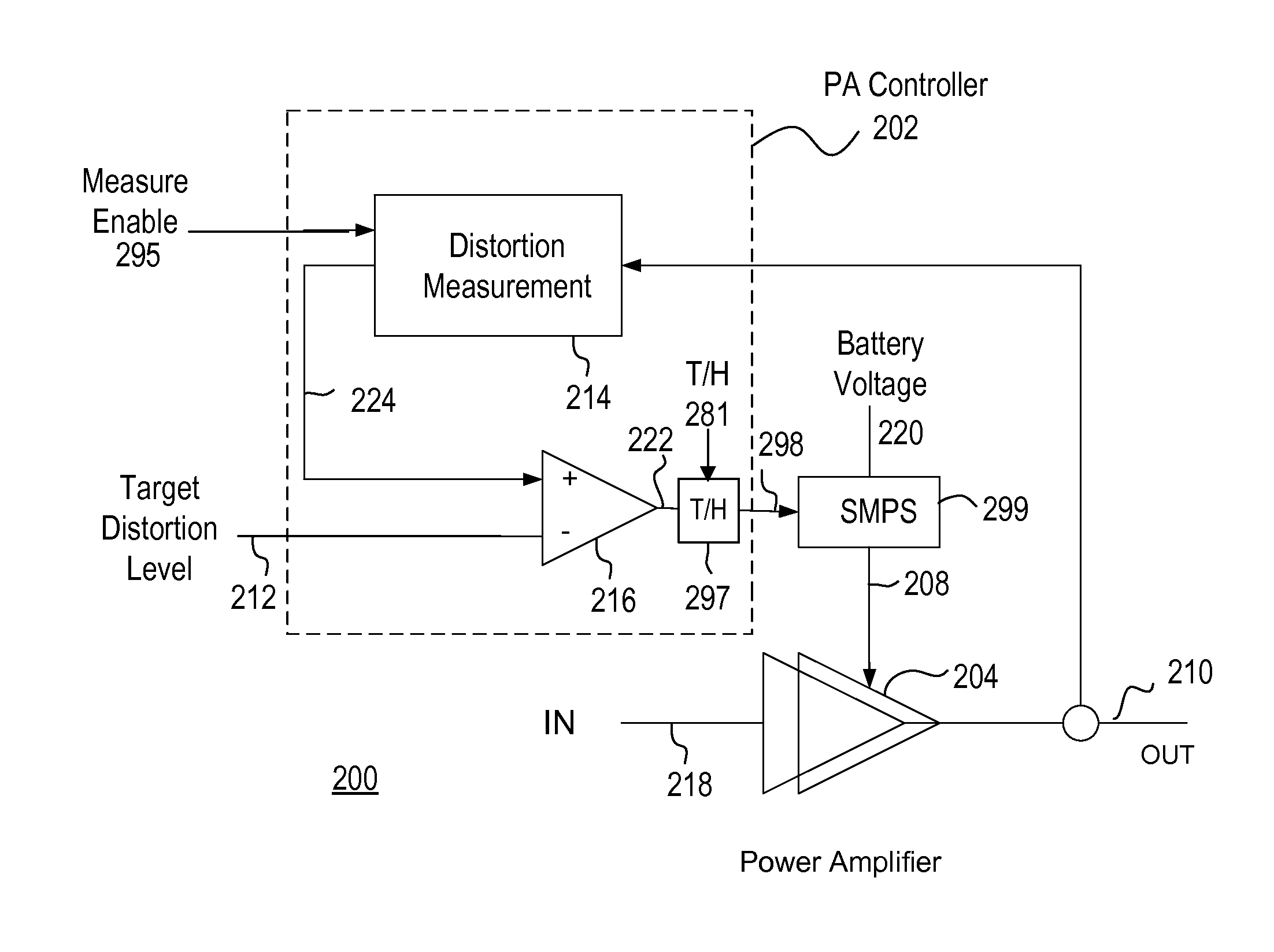
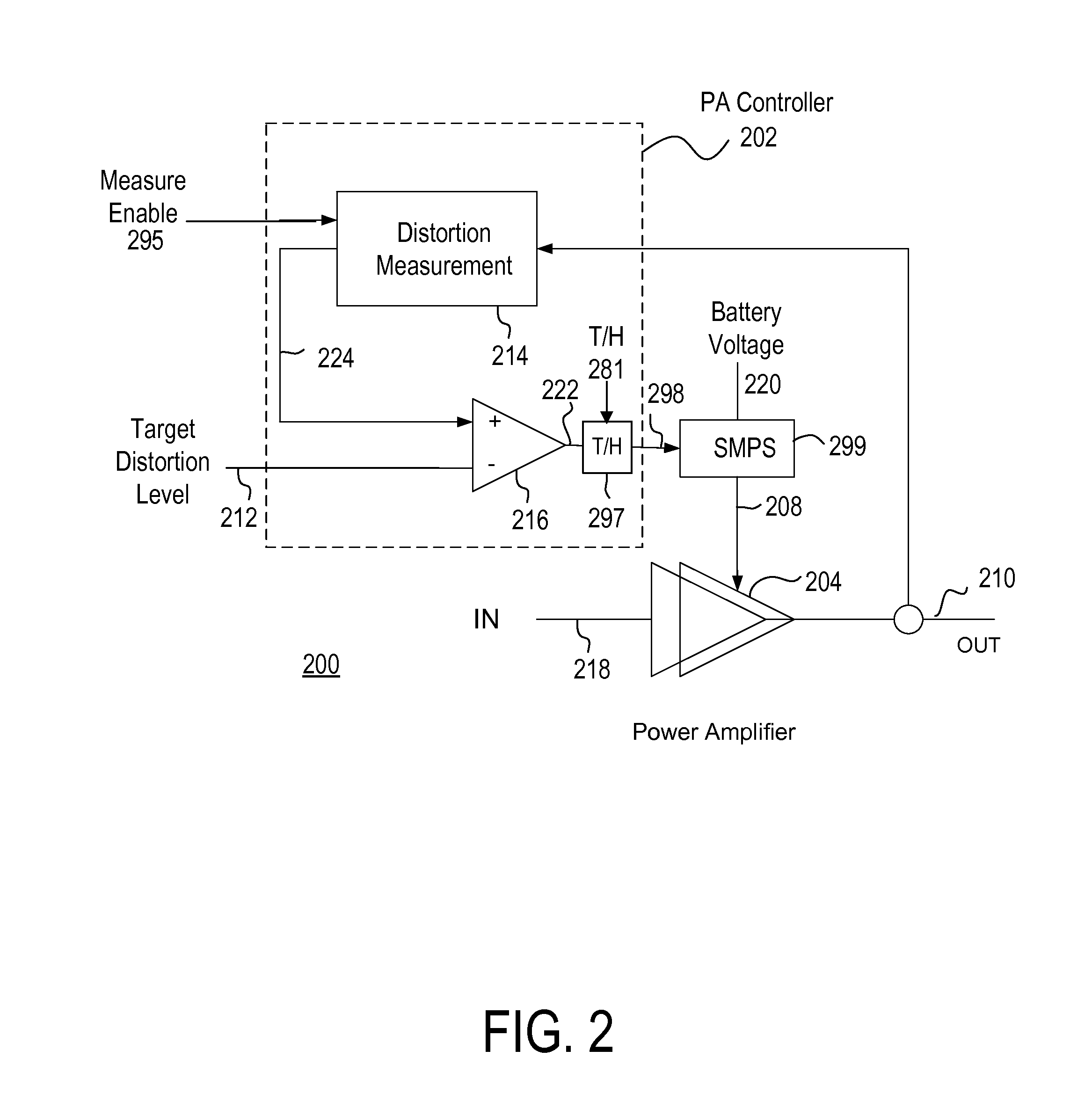
[0019]A power amplifier controller circuit includes a distortion measurement module for determining a measured distortion level of an output signal of a power amplifier (PA). A comparator compares the measured distortion level to a target distortion level and generates a power supply control signal indicative of the difference between the measured distortion level and the target distortion level. Based upon the power supply control signal, a power supply adjusts the supply voltage t

Problems solved by technology

RF PAs are one of the most significant sources of power consumption in these electronic devices, and their efficiency has a significant impact on the battery life of these portable electronic devices.
Since the RF spectrum is shared amongst users of the cellular telephone, a wide spectral occupancy is undesirable.
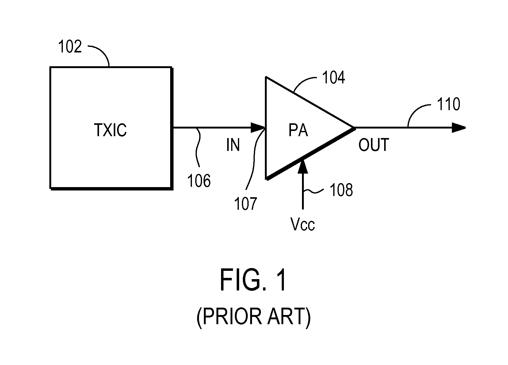
This typically results in power being wasted during the off-peak of the amplitude of the RF input signal 106, as the biasing remains fixed for the acceptable distortion at the peak power level.
Certain RF modulation techniques have evolved to require even more spectral efficiency, and thereby forcing the PA 104 to sacrifice more efficiency.
However, the EER technique often fails to provide significant efficiency gains, because the supply voltage 108 cannot be varied in an energy-efficient way to accommodate the large variations in the amplitude signal of the RF input signal 106; and thus, it fails to provide a substantial energy efficiency gain while maintaining the required linear amplification of the RF signal in the PA 104.
This is mainly due to the difficulty in realizing a fast, accurate, wide range, and energy efficient voltage converter to drive the supply voltage of the PA 104.
This results in no change in the overall battery power being consumed by the RF transmitter because any efficiency gained in the PA 104 is mostly lost in the linear regulator itself.
Variations of the EER technique, such as Envelope Following and other various types of polar modulation methods, likewise fails to result in any significant gain in efficiency in the RF transmitter, because the su

Method used


Image

  • Distortion-Driven Power Amplifier Power Supply Controller
  • Distortion-Driven Power Amplifier Power Supply Controller
  • Distortion-Driven Power Amplifier Power Supply Controller

Examples


Embodiment Construction

[0030]The Figures (FIG.) and the following description relate to preferred embodiments of the present invention by way of illustration only. It should be noted that from the following discussion, alternative embodiments of the structures and methods disclosed herein will be readily recognized as viable alternatives that may be employed without departing from the principles of the claimed invention.

[0031]Reference will now be made to several embodiments of the present invention(s), examples of which are illustrated in the accompanying figures. Wherever practicable similar or like reference numbers may be used in the figures and may indicate similar or like functionality. The figures depict embodiments of the present invention for purposes of illustration only. One skilled in the art will readily recognize from the following description that alternative embodiments of the structures and methods illustrated herein may be employed without departing from the principles of the invention d...


PUM


Abstract

A power amplifier controller measures the distortion of a power amplifier output. Based upon the distortion measured, the supply voltage to the PA is adjusted in a control loop. In one embodiment, distortion is measured by computing the ratio of the measured power in the output frequencies outside the desired output channel to the measured power in the output frequencies within the desired channel. If the distortion measured from the PA is higher than a target distortion level, the power supply voltage is raised. If the distortion measured from the PA is lower than the target distortion level, the power supply voltage is reduced. Thus, the supply voltage to the PA is maintained at the lowest possible voltage level, improving the efficiency of the PA.

Description

CROSS-REFERENCE TO RELATED APPLICATIONS[0001]This application claims priority under 35 U.S.C. § 119(e) from co-pending U.S. Provisional Patent Application No. 60 / 950,273 entitled “Distortion-Driven Power Amplifier Power Supply Controller” filed on Jul. 17, 2007, the content of which is incorporated by reference herein in its entirety.BACKGROUND[0002]1. Field of the Invention[0003]The present invention relates to a circuit for controlling RF PAs (Radio Frequency Power Amplifiers), and more specifically, to an RF PA controller circuit that adjusts the supply voltage of RF PAs.[0004]2. Description of the Related Art[0005]RF (Radio Frequency) transmitters and RF power amplifiers are widely used in portable electronic devices such as cellular phones, laptop computers, and other electronic devices. RF transmitters and RF power amplifiers are used in these devices to amplify and transmit the RF signals remotely. RF PAs are one of the most significant sources of power consumption in these e...

Claims


Application Information

Patent Timeline
IPC IPC(8): H03F1/32H03G3/20
CPCH03F1/0238H03G3/3042H03F1/32H03F2200/435
Inventor VINAYAK, VIKASDROGI, SERGE FRANCOISTOMASZ, MARTIN
Owner QUANTANCE
Why Eureka
Try Eureka