Fiber optic sensor and method for making
- Summary
- Abstract
- Description
- Claims
- Application Information
AI Technical Summary
Benefits of technology
Problems solved by technology
Method used
Image
Examples
example 1
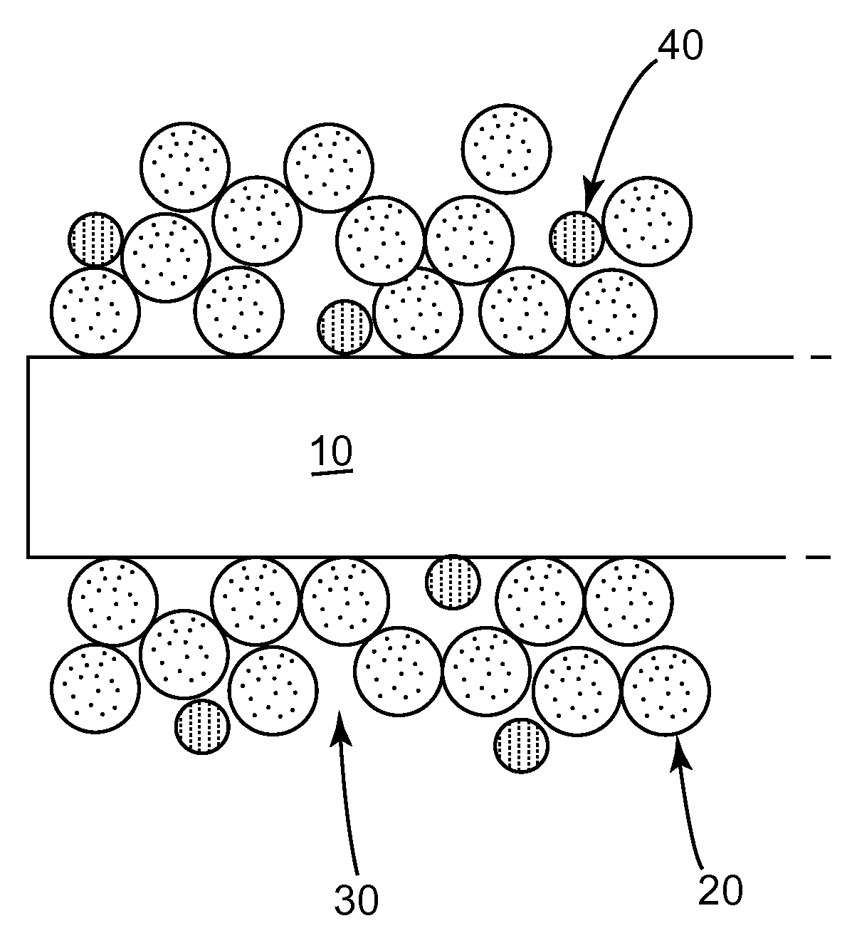
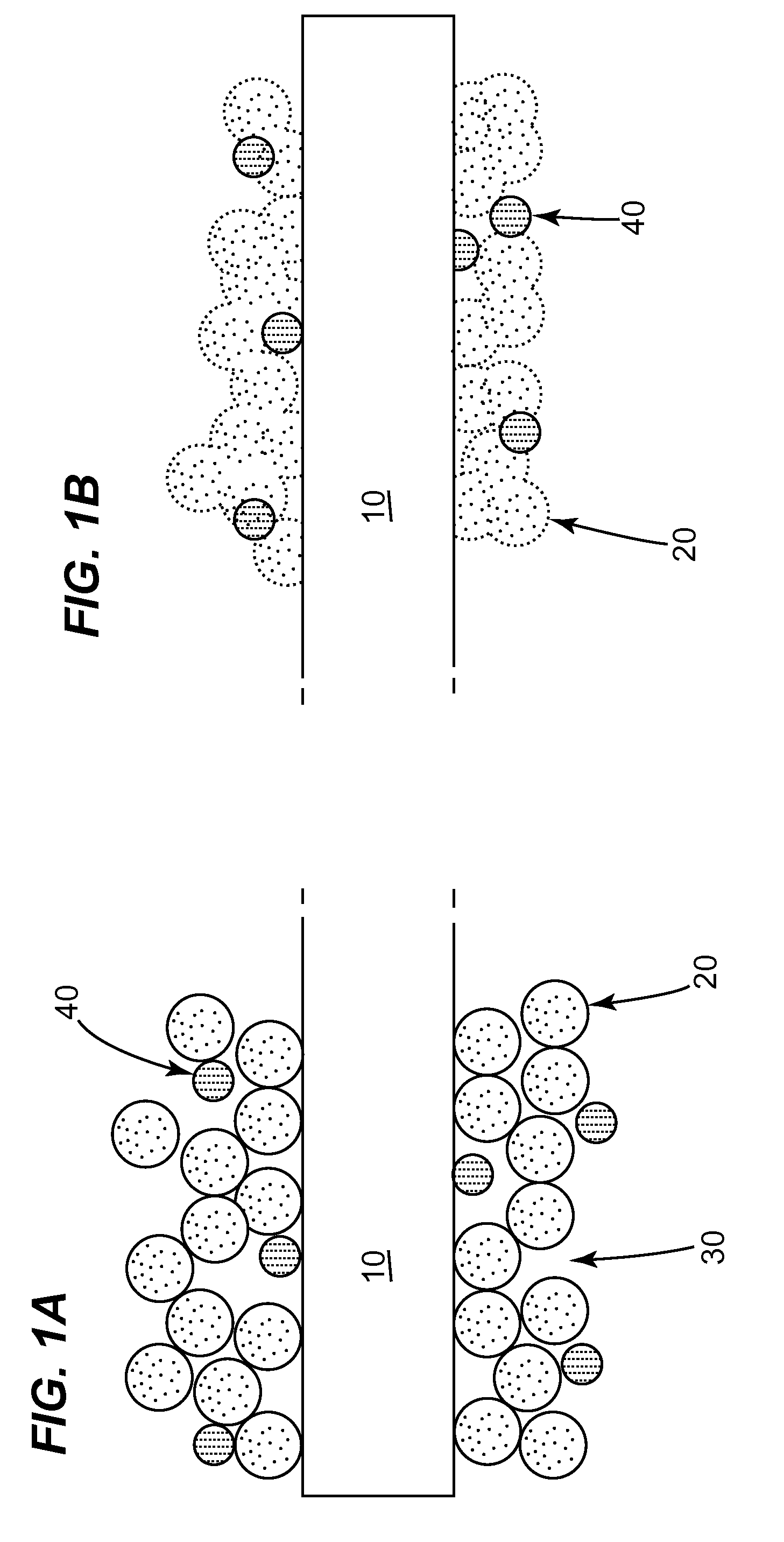
[0059]A mixture of 89.5 percent by weight tetraethoxyorthosilicate, 10.5 percent by weight palladium and 40 percent by weight based on the weight of the tetraethoxyorthosilicate and palladium of 1-propanol was prepared. A silica, having spherical particles with an average diameter of 300 nm where 95% of the particles have a diameter within 10% of the average diameter, was formed from the tetraethoxyorthosilicate and 1-propanol.
[0060]A film of the mixture of silica and palladium was applied to a glass substrate and heat treated at 400° C. for 2 hours. The film thickness was about 100 μm.
[0061]The fiber optic sensor was tested for hydrogen responses between room temperature and 525° C. FIGS. 3-8 show the H2 response optical reflection curve between alternating 5% H2 in N2 gas at 25° C. (room temperature), 120° C., 172° C., 355° C., 425° C. and 525° C., respectively. The sensor measured H2 sensing up to about 355° C.
[0062]The relative response to the H2 gas is summarized in FIG. 9. The...
example 2
[0065]A mixture of 80 percent by weight tetraethoxyorthosilicate, 15 percent by weight tin dioxide, 5 percent by weight palladium and 8 percent by weight based on the weight of the tetraethoxyorthosilicate, palladium and tin dioxide of 1-propanol was prepared. A silica, having spherical particles with an average diameter of 300 nm where 95% of the particles have a diameter within 10% of the average diameter, was formed from the tetraethoxyorthosilicate and 1-propanol.
[0066]A film of the mixture of silica, tin dioxide and palladium was applied to a glass substrate and heat treated at 400° C. for 2 hours. The film thickness was about 20 μm.
[0067]The fiber optic sensor was tested for carbon monoxide responses between 325° C. and 525° C. FIGS. 11 and 12 show the CO response optical reflection curve between alternating 5% CO in N2 gas at 425° C. and 525° C., respectively. The sensor measured CO sensing across the temperature range.
[0068]Additional testing of 1%, 2% and 3% CO was performe...
example 3
[0069]A mixture of 89.5 percent by weight tetraethoxyorthosilicate, 10.5 percent by weight palladium and 20 percent by weight based on the weight of the tetraethoxyorthosilicate and palladium of 1-propanol was prepared. A silica, having spherical particles with an average diameter of 300 nm where 95% of the particles have a diameter within 10% of the average diameter, was formed from the tetraethoxyorthosilicate and 1-propanol.
[0070]A film of the mixture of silica and palladium was applied to a glass substrate and heat treated at 500° C. for 2 hours. The film thickness was about 100 μm.
[0071]The fiber optic sensor was tested for carbon monoxide responses from room temperature to 525° C. There was no signal for CO measurement at room temperature, but there were good signal outputs for the high temperatures. FIGS. 13 and 14 show the CO response optical absorption curve between alternating 5% CO in N2 gas at 280° C. and 525° C., respectively. As shown in FIG. 14, the response to the CO...
PUM
| Property | Measurement | Unit |
|---|---|---|
| Temperature | aaaaa | aaaaa |
| Temperature | aaaaa | aaaaa |
| Time | aaaaa | aaaaa |
Abstract
Description
Claims
Application Information
 - R&D
- Intellectual Property
- Life Sciences
- Materials
- Tech Scout
- Unparalleled Data Quality
- Higher Quality Content
- 60% Fewer Hallucinations
Browse by: Latest US Patents, China's latest patents, Technical Efficacy Thesaurus, Application Domain, Technology Topic, Popular Technical Reports.
© 2025 PatSnap. All rights reserved.Legal|Privacy policy|Modern Slavery Act Transparency Statement|Sitemap|About US| Contact US: help@patsnap.com


