

Battery module, assembled battery, and vehicle including these batteries
- Summary
- Abstract
- Description
- Claims
- Application Information
AI Technical Summary
Benefits of technology
Problems solved by technology
Method used
Image

Examples
first embodiment
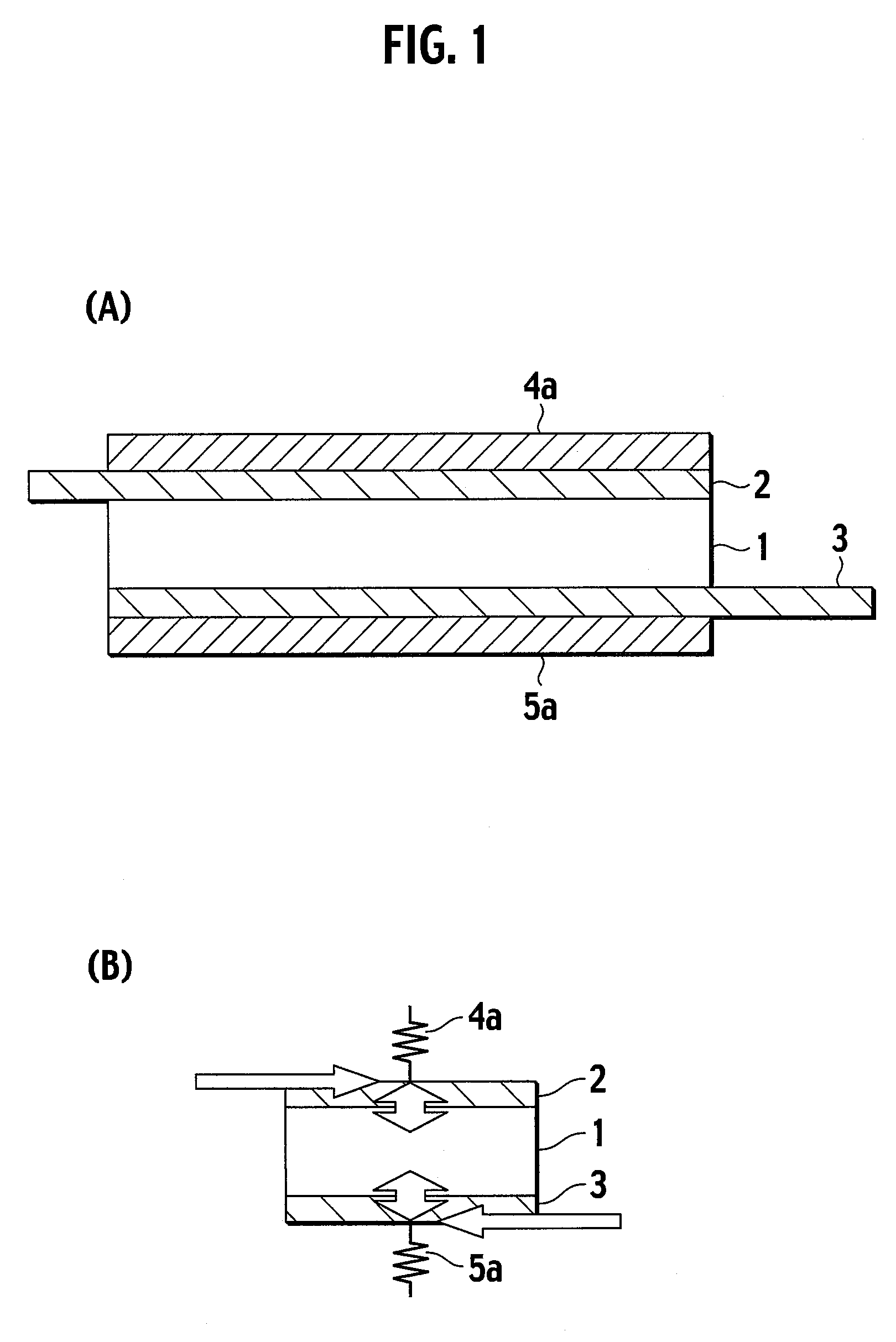
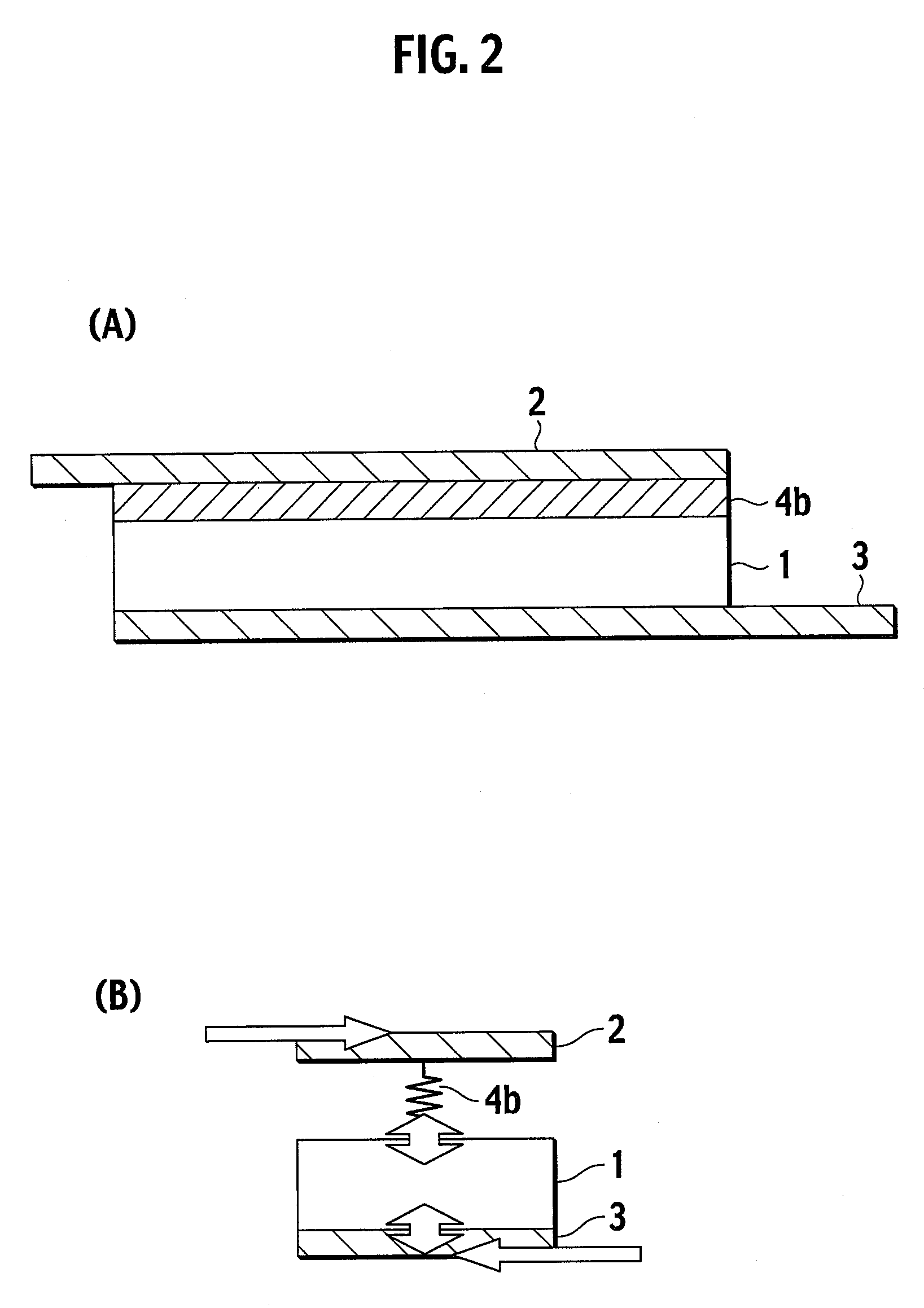
[0043]FIGS. 1(A) and 1(B) are a schematic view illustrating the structure of a conventional battery module disclosed in Japanese Laid-Open Patent Publication No. 2002-110239. FIGS. 2(A) and 2(B) are a schematic view illustrating the structure of the battery module according to the present invention having a structure in which a flat-type battery and a positive electrode tab sandwich an electron-conductive elastic member. FIGS. 3(A) and 3(B) are a schematic view illustrating the structure of the battery module according to the present invention having a structure in which a flat-type battery and a positive electrode tab sandwich an electron-conductive elastic member and the flat-type battery and a negative electrode tab sandwich an electron-conductive elastic member, respectively. FIGS. 4(A) and 4(B) are a schematic view illustrating the structure of the battery module according to the present invention having a structure in which two layered flat-type batteries sandwich an electron-...
second embodiment
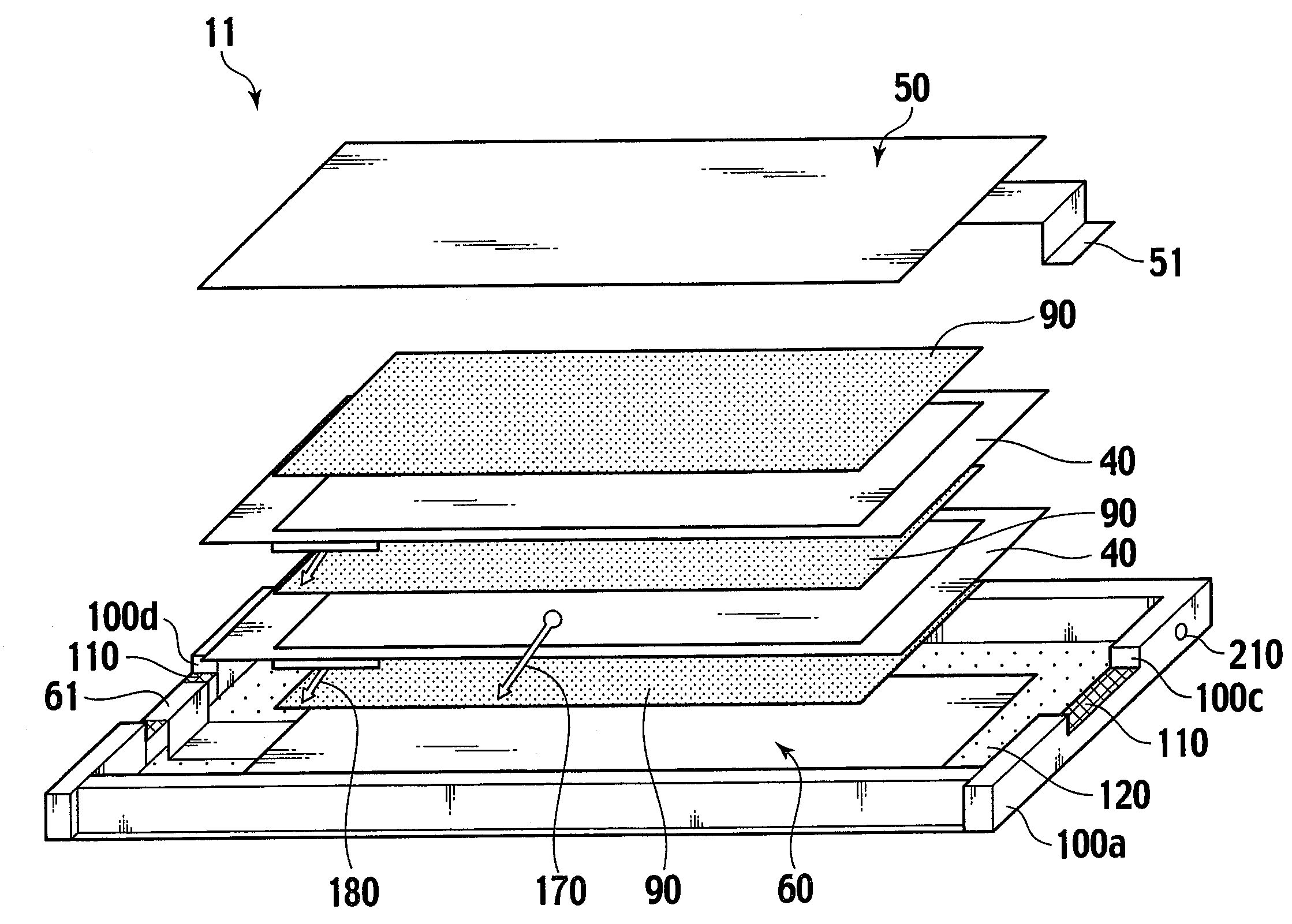
[0058]FIG. 6 is a cross-sectional view illustrating the layered structure of a battery module 11 according to the second embodiment of the present invention. FIG. 7 is a cross-sectional view illustrating a bipolar battery 40 shown in FIG. 6. FIG. 8 is a cross-sectional view illustrating a bipolar electrode 21. FIG. 9 is a cross-sectional view for the description of an electric cell layer 26. FIG. 10 illustrates, in a stepwise manner, the manufacture process of an electrolyte layer 25 in which a separator 25a includes a seal section 30. FIG. 10(A) is a schematic top view illustrating the separator 25a forming a base of the electrolyte layer 25. FIG. 10(B) is a schematic top view illustrating the seal section 30 formed at the outer periphery of the separator 25a. FIG. 10(C) is a schematic top view illustrating an electrolyte section 25b formed at the inner side of the seal section 30 of the separator 25a to complete the electrolyte layer 25. FIG. 10(D) is a cross-sectional view taken ...
third embodiment
[0123]With reference to FIG. 18, the battery module 13 of the third embodiment has a structure in which two battery groups obtained by layering the two bipolar batteries 40 in the up-and-down direction to electrically serially connect the bipolar batteries 40 are arranged in a direction orthogonal to the layered direction of the bipolar electrode 21. The two battery groups are arranged so as to have the same electrical polarity (the upper side in FIG. 18 is the positive electrode and the lower side is the negative electrode) and are electrically parallely connected via the upper electrode tab 50 and the lower electrode tab 60. This electrical connecting formation is called “two parallel×two serial”.
[0124]In the third embodiment, the bipolar batteries 40 are electrically connected in a series-parallel manner. Thus, a requirement related to the output and capacity can be satisfied easily by merely changing the number of the bipolar batteries 40 to be serially connected and the number ...
PUM
 Abstract
Description
Claims
Application Information