
Tissue Dissection Method

a cannula and tissue technology, applied in the field of cannula separation of tissue, can solve the problems of blood vessel avulsion and trauma to tissue and internal organs, difficulty in everting balloon type, and difficulty in reducing visual distortion

Inactive Publication Date: 2009-01-22
MAQUET CARDIOVASCULAR LLC
View PDF98 Cites 29 Cited by
  • Summary
  • Abstract
  • Description
  • Claims
  • Application Information

AI Technical Summary

Benefits of technology

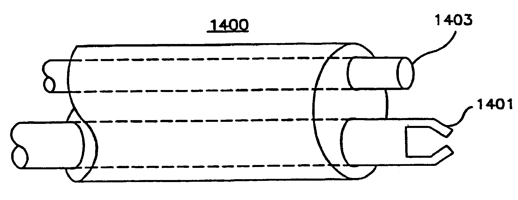
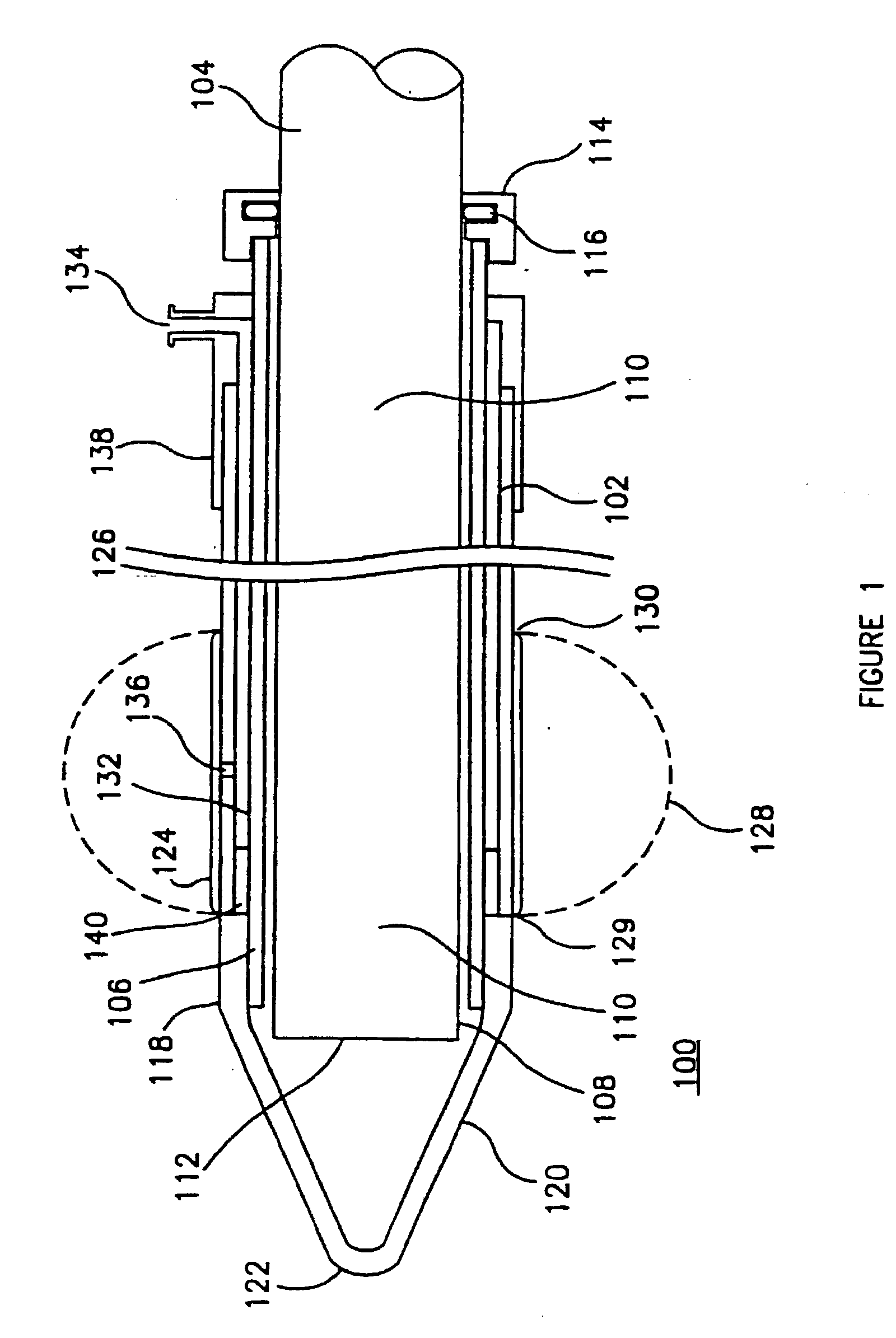
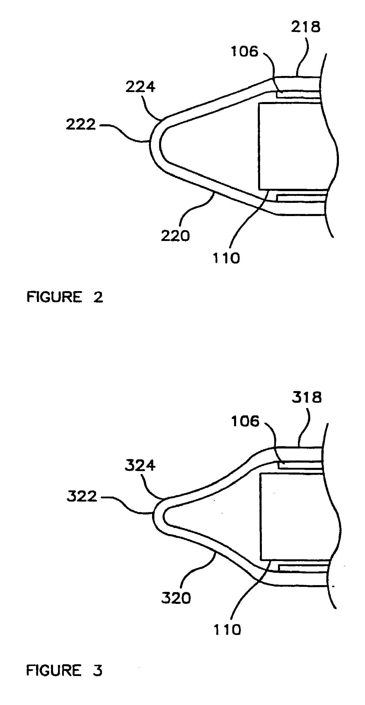
[0011]The present invention provides a cannula for bluntly dissecting an elongated cavity in tissue particularly along the course of a vessel in a human or animal body. The cannula includes a tubular body having proximal closed end and distal blunt end and at least one lumen extending the length of the body. The cannula also includes an endoscope having a lighted, viewing end disposed in the lumen near the distal end of the body, and includes a transparent, tissue separating member, or blunt tip, substantially covering and selectively removable from the distal end of the body. The tissue separating member or blunt tip disposed on the distal end of the body includes internal walls that taper and end in a sharp point to reduce visual distortion through the endoscope that is optically aligned with the tip.

Problems solved by technology

The force exerted by the passage of mechanical probes may lead to blood vessel avulsion and trauma to tissue and internal organs.
The problem becomes acute when dissecting and harvesting blood vessels having a small diameter of about 3 to 8 mm.
An everting type of balloon encounters difficulties when dissecting tissue adjacent a smaller-diameter vessel.
However, an endoscope used in conjunction with those disclosed catheters is unable to monitor the dissection process, since the endoscope lies within the central lumen proximal to the everting balloon.
Thus, an endoscope in the central lumen of existing double-lumen, everting balloon catheters is unable to view the area of tissue separation, since a double layer of balloon membrane lies between the endoscope and the tissue and blocks the endoscopic line of sight.
Control of the dissection is difficult because visualization of the vessel is obscured by the collapse of the tissue planes into the area between the cutting element and the endoscope.
Furthermore, the risk of side vessel avulsion or trauma to the vessel is greatly increased by the orientation of the outwardly extending cutting elements.
However, the failure of the endoscope to enlarge a cavity adjacent the blood vessel obscures viewing of the dissection area and manipulation of the vessel therein.
The position of the viewing image relative to the tissue dissection area could obscure the identification of side vessels leading to an increased risk of vessel avulsion.

Method used


Image

  • Tissue Dissection Method
  • Tissue Dissection Method
  • Tissue Dissection Method

Examples


Embodiment Construction

[0033]In accordance with one embodiment of the present invention, a cannula includes a tubular body having proximal closed end and distal blunt end, at least one lumen extending the length of the body, an endoscope having a lighted, viewing end disposed in the lumen near the distal end of the body, and a transparent, tissue separating member substantially covering the distal end of the body and selectively removable from the distal end. The present invention also includes methods for using such a cannula for separating tissue to form an elongated cavity along the course of a small blood vessel and subsequently harvesting the blood vessel, or using the blood vessel as an in-situ graft.

[0034]FIG. 1 shows an embodiment of the cannula 100 of the present invention. The cannula 100 includes a tubular body 102 having a proximal end 104 and a distal end 106. At least one lumen 108 extends the length of the body 102. Disposed in the lumen 108 is an endoscope 110 having a lighted, viewing end...


PUM


Abstract

A cannula includes a tubular body and an endoscope for viewing through a transparent, blunt, tissue-separating tip substantially covering the distal end of the body. Endoscopic viewing through the tip is enhanced by inner walls that taper to a cusp adjacent the blunt tip in order to reduce visual distortion. Alternatively, a cannula includes a dissection probe and a removable or deflectable tip for exposing the probe and endoscope to facilitate viewing and the dissection of connective tissue and lateral vessels along the dissected cavity. Methods of using such cannulas produce an elongated cavity along the course of a vessel for subsequent harvesting or other treatment of the isolated vessel. Lateral branch vessels of a main vessel to be harvested are doubly clipped or otherwise doubly occluded, and then severed to isolate the main vessel for use, for example, in revascularizing the coronary artery.

Description

RELATED APPLICATION[0001]This application is a continuation of application Ser. No. 10 / 267,202, filed on Oct. 8, 2002 which is a continuation of application Ser. No. 09 / 750,848, filed on Dec. 27, 2000, now abandoned, which is a continuation of Ser. No. 09 / 249,249, filed on Feb. 11, 1999, and now issued as U.S. Pat. No. 6,264,670, which is a divisional application of application Ser. No. 08 / 907,691 filed on Aug. 8, 1997, and now issued as U.S. Pat. No. 5,980,549, which is a continuation-in-part application of application Ser. No. 08 / 593,533 filed on Jan. 24, 1996, now also abandoned, which is a continuation of application Ser. No. 08 / 502,494, filed on Jul. 13, 1995, now issued as U.S. Pat. No. 5,683,409, and the subject matter hereof is related to the subject matter of application Ser. No. 08 / 421,481, filed on Apr. 12, 1995, now issued as U.S. Pat. No. 5,591,183, which prior applications are assigned to the same assignee as the present application.FIELD OF THE INVENTION[0002]The pres...

Claims


Application Information

Patent Timeline
Patent Type & Authority Applications(United States)
IPC IPC(8): A61B17/3209A61M13/00A61B1/018A61M29/02A61B17/00A61B17/02A61B17/11A61B17/32A61B17/34A61B19/00
CPCA61B17/00008A61B17/0218A61B17/11A61B17/320016A61B17/3417A61B2017/320048A61B19/5212A61B2017/00243A61B2017/00473A61B2017/00969A61B2017/320044A61B19/52A61B90/36A61B90/361
Inventor CHIN, ALBERT K.
Owner MAQUET CARDIOVASCULAR LLC
Learn More