Variable-airflow cloth, sound absorbing material, and vehicular part

a technology of airflow cloth and sound absorption material, applied in the field of cloth, can solve the problems of electrolysis, excessive energy, and performance decline due to leakage of electrolytic solution, and achieve the effect of reducing weight and saving spa

Active Publication Date: 2009-01-29
NISSAN MOTOR CO LTD
View PDF8 Cites 25 Cited by
  • Summary
  • Abstract
  • Description
  • Claims
  • Application Information

AI Technical Summary

Benefits of technology

[0012]The present invention has been made in consideration for the conventional problems as described above. It is an object of the present invention to obtain cloth capable of controlling the air permeability by a control factor enabling the weight reduction and the space saving in comparison with the conventional mechanical variable mechanism.

Problems solved by technology

However, in general, many of these mechanical drive sources are made of metal and largely occupy a mass and a space.
Moreover, also in necessary power sources, there are many which require excessive energy.
However, in this example, a gel actuator that drives primarily in the solvent is made to drive in the air, and accordingly, it is necessary to hold, as a system, the actuator together with a solvent bath, and there is a possibility that a performance decrease owing to leakage of an electrolytic solution and to electrolysis may occur.

Method used


Image

  • Variable-airflow cloth, sound absorbing material, and vehicular part
  • Variable-airflow cloth, sound absorbing material, and vehicular part
  • Variable-airflow cloth, sound absorbing material, and vehicular part

Examples


example 1

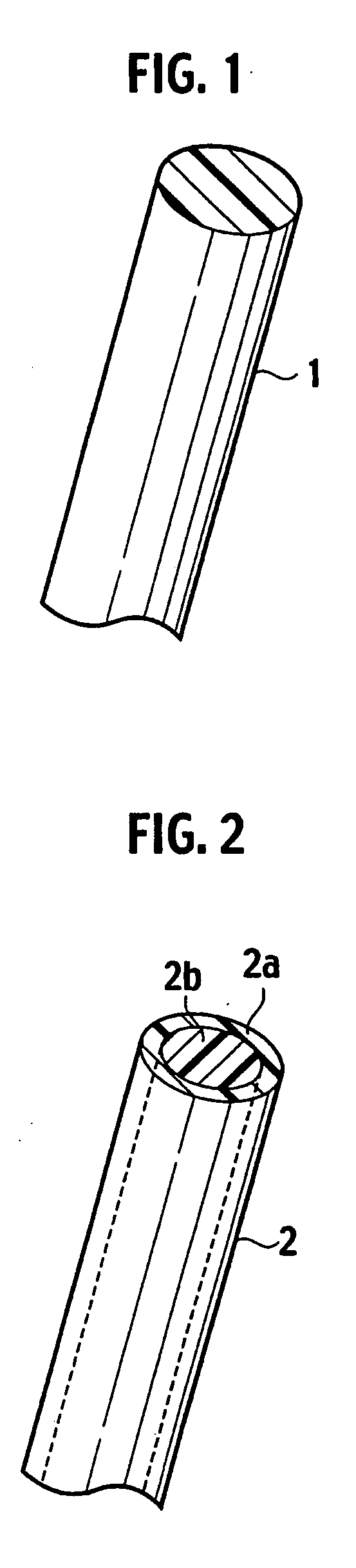
[0153]Electrical-conductive polymeric fibers were fabricated by a wet spinning method. Specifically, acetone (Code No. 019-00353, made by Wako Pure Chemical Industries, Ltd.) was used for a solvent phase, and PEDOT / PSS (Baytron P (registered trademark)) as an electrical-conductive polymeric component was extruded from a microsyringe (MS-GLL100 made by Ito Corporation; inner diameter of needle portion: 260 μm) at a speed of 0.5 mL / h, whereby electrical-conductive polymeric fibers with a diameter of approximately 10 μm were obtained. Next, an aqueous polyester emulsion (AA-64, made by Nippon NSC Ltd.) was applied on surfaces of the fibers, followed by drying at 25° C. for 24 hours. Composite fibers thus obtained had a crescent cross-sectional shape of a stack type, and a diameter thereof was approximately 17 μm.

[0154]Next, a web was formed of mixed fibers composed of 80 mass % of the composite fibers cut to an average cut length of 50 mm and 20 mass % of binder fibers [core component:...

example 2

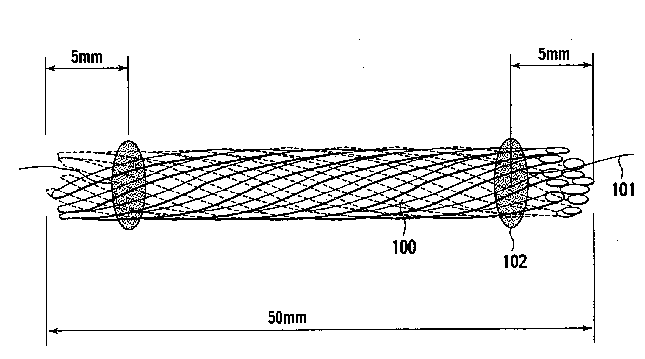
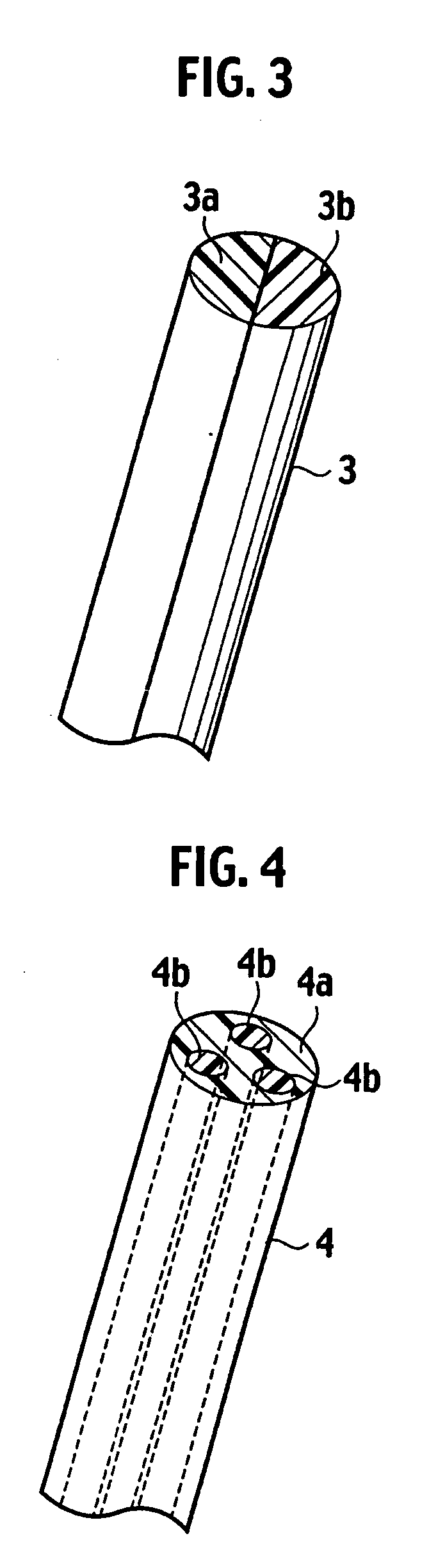
[0157]Composite fibers were fabricated by a wet spinning method similar to that in Example 1. Specifically, acetone was used for a solvent phase, and PEDOT / PSS (Baytron P (registered trademark)) as an electrical-conductive polymeric component and an aqueous solution prepared by diluting a water dispersion (Product No. 56122-3 made by Aldrich Corporation) of polystyrenesulfonate (PSS) to 10 times were extruded from two microsyringes (MS-GLL100 made by Ito Corporation; inner diameter of needle portion: 260 μm) at a speed of 0.5 mL / h into the same solvent phase. In such a way, composite fibers were obtained, in which a cross section had a shape shown in (n) of FIG. 13, and a length of the longest portion of the cross section was approximately 14 μm. In a wet spinning machine 90 shown in FIG. 40, such spinning raw liquids were extruded from two wet spinning mouthpieces 91, and extruded precursors 92 of the composite fibers were made to pass through a wet spinning solvent bath 93 that co...

example 4

[0160]By a wet spinning method similar to that in Example 2, composite fibers were obtained, in which a length of the longest portion of a cross section was approximately 14 μm. Next, 100 composite fibers thus obtained were bundled to form an aggregate. Next, a web was formed of mixed fibers composed of 80 mass % of the aggregate of the fibers cut to an average cut length of 50 mm and 20 mass % of binder fibers [core component: PET; sheath component: copolymer polyester (amorphous polyester); softening point: 110° C.] with a diameter of 14 μm by the airlaid method. Then, the web was compressed to a specific thickness (approximately 8 mm), and was then heated at 160° C. for seven minutes, whereby cloth with an average apparent density of 0.025 g / cm3 and a thickness of 10 mm was obtained. By using this cloth, variable-airflow cloth was obtained in a similar way to Example 1.


PUM

PropertyMeasurementUnit
softening pointaaaaaaaaaa
diameteraaaaaaaaaa

Abstract

Cloth, in which air permeability is variable by energization, includes: a fibrous object composed of composite fibers, each of the composite fibers including: an electrical-conductive polymeric material; and a material different from the electrical-conductive polymeric material, the different material being directly stacked on the electrical-conductive polymeric material; and electrodes which are attached to the fibrous object, and energize the electrical-conductive polymeric material. Each of the composite fibers has a structure in which the material different from the electrical-conductive polymeric material is stacked on at least a part of a surface of the electrical-conductive polymeric material, or a structure in which either one of the electrical-conductive polymeric material and the material different from the electrical-conductive polymeric material penetrates the other material in a longitudinal direction. The cloth is capable of controlling the air permeability by a control factor enabling weight reduction and space saving.

Description

TECHNICAL FIELD[0001]The present invention relates to cloth in which air permeability is variable by energization. More specifically, the present invention relates to cloth in which the air permeability is reversibly varied by the energization, and to a sound absorbing material and a vehicular part, which use such cloth.BACKGROUND ART[0002]Heretofore, many functional materials have been developed. Among them, in functional commercial products, development in which a fiber material, a cloth structure, functional post-treatment and the like are combined has also be progressed positively in order to allow the products to develop higher and newer functions.[0003]In new functional fibers in recent years, complexing and upgrading thereof have advanced. Moreover, in the apparel industry, many proposals have been made on fibers in which functions are changed in response to a change of a wearing environment, that is, which include so-called dynamic functionality. A thermal storage material t...

Claims


Application Information

Patent Timeline
Patent Type & Authority Applications(United States)
IPC IPC(8): D04H13/00B29C65/18B60R13/08D04H1/4382D04H1/542G10K11/16G10K11/162
CPCA41D27/28Y10T428/2922D01D11/06D01F8/16D03D1/0064D03D9/00D03D15/00D03D15/0027D03D15/0083D06M15/507D10B2321/10D10B2331/02D10B2331/04D10B2401/041D10B2401/046D10B2401/16D04B1/16Y10T428/2924Y10T428/2929Y10T428/2925Y10T428/2931Y10T428/2913Y10T428/2915A41D2400/20A41D31/14Y10T442/3992Y10T442/629Y10T442/641Y10T442/3146Y10T442/627Y10T442/637Y10T442/444Y10T442/3154Y10T442/696Y10T442/3976Y10T442/638
Inventor MIURA, HIROAKI
Owner NISSAN MOTOR CO LTD
Why Eureka
Try Eureka