Implantable sensor method and system

Active Publication Date: 2009-01-29
MEDTRONIC MIMIMED INC
View PDF99 Cites 275 Cited by
  • Summary
  • Abstract
  • Description
  • Claims
  • Application Information

AI Technical Summary

Benefits of technology

[0010]Embodiments of the present invention relate to systems and methods for non-vascular sensor implantation and to a system and method for accurately m

Problems solved by technology

However, vascular placement of a physiological parameter sensor may suffer from several disadvantages.
A physiological parameter sensor is not inserted into a vein without great difficulty and painstaking effort by an attending physician.
Moreover, a physiological parameter sensor is not adjusted within or extracted from a vein without similar difficulty and effort.
Such an environment may have several detrimental effects on the sensor.
Due to constant fluidic contact, the sensor may suffer from decreased sensitivity, stability and effective life.
Should a characteristic of the sensor be diminished to an extent rendering the sensor ineffective, the sensor must be removed and replaced, introducing the difficul

Method used


Image

  • Implantable sensor method and system
  • Implantable sensor method and system
  • Implantable sensor method and system

Examples


Example

[0046]In the following description of preferred embodiments, reference is made to the accompanying drawings which form a part hereof, and in which are shown by way of illustration specific embodiments in which the invention may be practiced. It is to be understood that other embodiments may be utilized and structural changes may be made without departing from the scope of the preferred embodiments of the present invention.

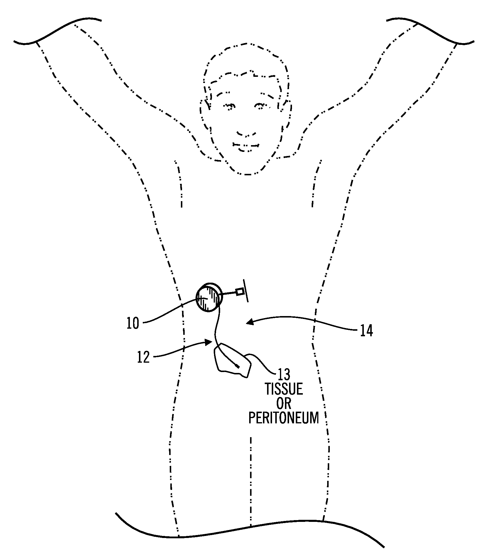
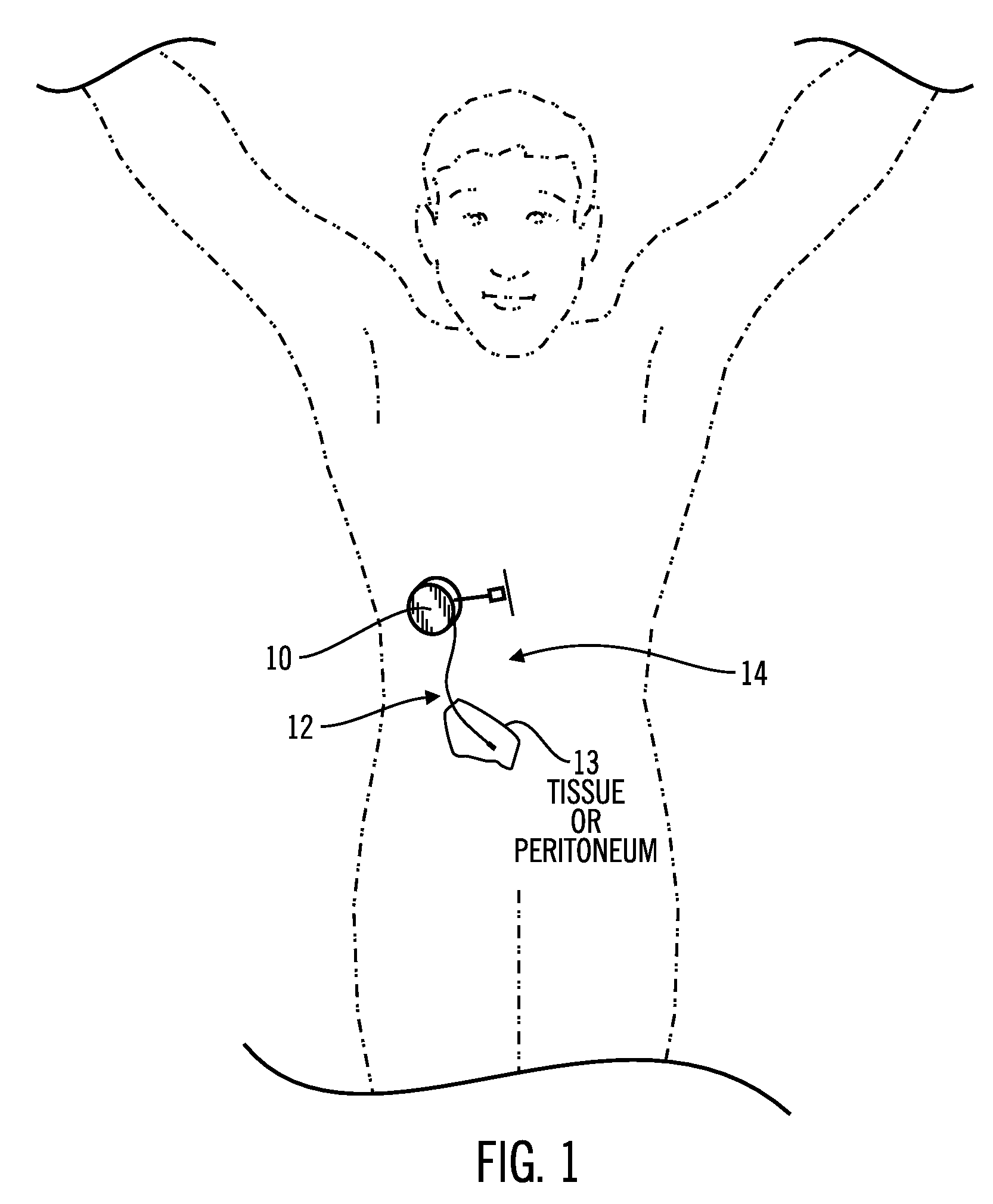
[0047]FIG. 1 shows a general placement of an implant unit 10 and a sensor 12 in the human body according to an embodiment of the present invention. The implant unit 10 may be placed into a human body in a variety of locations such as, for example, adjacent to the abdominal cavity 14, or in other locations such as, for example, the spinal cavity or chest cavity. A sensor 12 connecting to the implant unit 10 may be located in the peritoneum 13, the membrane lining the abdominal cavity and connecting and supporting internal organs; in subcutaneous tissue 13, i.e., tis...


PUM


Abstract

Systems and methods for non-vascular sensor implantation and for measuring physiological parameters in areas of a body where the physiological parameters are heterogeneous. An implant unit is implanted in an area of a body and a foreign body capsule is allowed to form around the implant unit area. A sensor may be directed into a body cavity such as, for example, the peritoneal space, subcutaneous tissues, the foreign body capsule, or other area. A subcutaneous area of the body may be tunneled for sensor placement. Spatially separated sensing elements may be used for detecting individual amounts of the physiological parameter. An overall amount of the physiological parameter may be determined by calculating a statistical measurement of the individual sensed amounts in the area. Another embodiment of the invention, a multi-analyte measuring device, may include a substrate having an electrode array on one side and an integrated circuit on another side.

Description

CROSS-REFERENCE TO RELATED APPLICATIONS[0001]Embodiments of the present invention relate to U.S. application Ser. No. 10 / 034,627, filed Dec. 27, 2001 and U.S. Provisional Application Ser. No. 60 / 335,627, filed Oct. 23, 2001, each entitled “Method and System for Non-Vascular Sensor Implantation,” each of which is incorporated by reference herein, and from a U.S. Provisional Application, Ser. No. 60 / 414,290, filed Sep. 27, 2002, entitled “Implantable Sensor Method and System,” which is also incorporated by reference herein and is a basis for a claim of priority.BACKGROUND[0002]1. Field of the Invention[0003]The present invention relates to the field of in vivo sensors and, in particular, to in vivo sensors that are implanted in non-vascular areas of the body. The present invention also relates to a system and method for accurately measuring a physiological parameter in areas of a body (or external to the body) where amounts of the physiological parameter are heterogeneous in nature.[0...

Claims


Application Information

Patent Timeline
IPC IPC(8): A61B5/145A61B5/00A61B17/34A61K9/22A61M1/16A61M5/142
CPCA61B5/0031A61M5/1723A61B5/14532A61B5/14865A61B5/6882A61B17/3468A61M1/1698A61M5/14276A61M2230/20A61M2230/201A61B5/04A61B5/14503A61B5/14552A61B5/6847A61B5/145
Inventor MILLER, MICHAEL E.SHAH, RAJIV
Owner MEDTRONIC MIMIMED INC
Why Eureka
Try Eureka