Architectural physical synthesis

a technology of architectural physical synthesis and integrated circuits, applied in the direction of instruments, computing, electric digital data processing, etc., can solve the problems of not meeting the circuit design criteria, the physical layout of the circuit becomes significant, and the delay of the interconnection becomes significant, so as to improve the quality of timing and available resource estimation, improve placement metrics, and improve implementation quality

Active Publication Date: 2009-01-29
SYNOPSYS INC
View PDF18 Cites 40 Cited by
  • Summary
  • Abstract
  • Description
  • Claims
  • Application Information

AI Technical Summary

Benefits of technology

[0019]In another embodiment, the refinements transforms also have an urgency metric based on the quality of alternative implementations and are selected in order of urgency. The quality of an implementation is measured in terms of design objectives like area consumption, power consumption or timing. Other more esoteric objectives like single event upset hardness can also be included. For example, if a design contains one large memory and several small sized memories, and the large memory has a relatively poor implementation quality when implemented by the logic fabric, it is relatively much more important to associate the large memory with scarce special purpose memory resources on the chip than the medium sized memories in the design. The urgency metric for the large memory would then be much higher than the metric for the small memories. Once components are mapped to a specific implementation and associated with specific resources on the chip, the connections to these components act as anchors for the placement of the remainder of the circuit, improving the quality of the timing and available resource estimation.
[0020]In one embodiment, the placement transform can be a refinement of location of one or more placeable objects, to improve placement metrics such as: instance congestion, routability, and circuit performance. A placeable object may consist of a Behavioral synthesis component, an RTL block of unmapped logic, mapped logic, or any combination of these.
[0031]In another embodiment, the applied transforms and their potential alternatives are recorded. The flow may be repeated and the alternative transforms can be applied to achieve better results.

Problems solved by technology

However, with shrinking technology nodes, the interconnect delays become significant, surpassing the gate delays.
This results in the delay estimation in the synthesis operation becoming less and less correlated to the actual delays following placement and routing operations, leading to the lack of timing predictability between post-synthesis and post-layout results.
Thus in many cases, after the placement and routing processes, the circuit physical layout cannot meet the circuit design criteria, and often the designers must start over from the synthesis step and repeat the synthesis / placement / routing processes.
Producing a good quality floorplan manually is challenging and requires skilled users.
Because synthesis is decoupled and follows the automatic floorplanning, the accuracy of the timing and area information is poor during the floorplanning.
Critical paths are re-optimized but because detail placement is not updated, interconnect delays for modified nets revert to statistical models.
If many changes are made, then the following legalization of the resulting netlist may require moving instances far from their initial positions, resulting in large delay estimation errors.
For this reason IPO is seen as unstable when significant changes are required to achieve timing closure.
A limitation of this technique is that individual changes are limited to modest increases in resources or the instability problem of the IPO technique re-surfaces.

Method used


Image

  • Architectural physical synthesis
  • Architectural physical synthesis
  • Architectural physical synthesis

Examples


Embodiment Construction

[0052]Methods and apparatuses for designing an integrated circuit or a plurality of integrated circuits are described herein. In the following description, for purposes of explanation, numerous specific details are set forth in order to provide a thorough understanding of the present invention. It will be evident, however, to one skilled in the art that the present invention may be practiced without these specific details. In other instances, well-known structures, processes and devices are shown in block diagram form or are referred to in a summary manner in order to provide an explanation without undue detail.

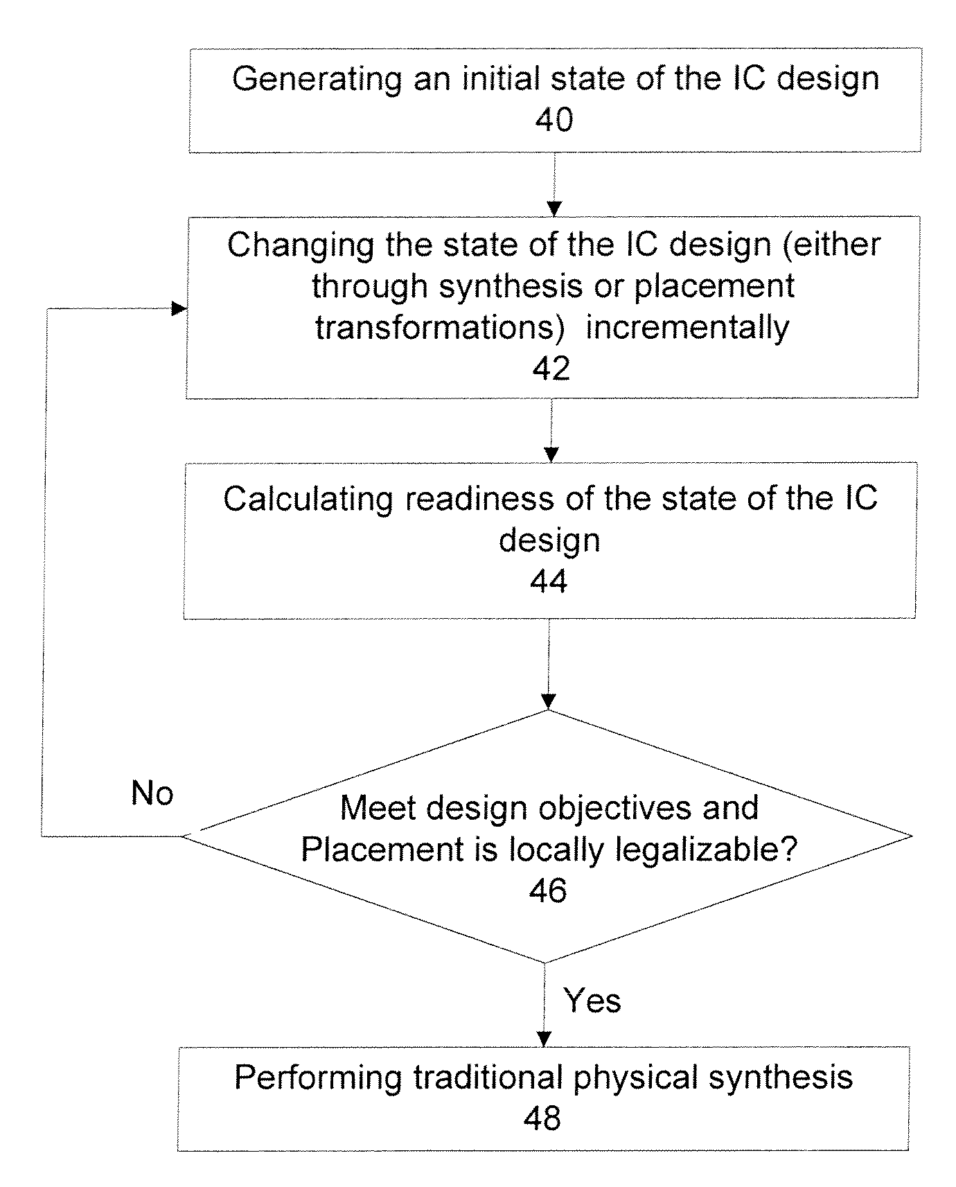
[0053]The present invention discloses methods and apparatuses to design an integrated circuit which, in one embodiment, combines placement and synthesis in a single pass. An embodiment of the present invention discloses a physical synthesis process, termed Architectural Physical Synthesis, where the interaction between the synthesis and the placement occurs in an architectura...


PUM


Abstract

The present invention discloses methods and apparatuses to design an integrated circuit. According to one aspect, the present invention circuit design discloses an iterative process of synthesis and placement where each iteration provides incremental changes on the design of the integrated circuit. The incrementally iterative approach of the present invention provides a continuous advancement from synthesis to placement and vice versa, with the incremental improvements on synthesis made with knowledge of current instance placement, and the incremental improvements on placement made with knowledge of current circuit logic. According to another aspect, the present invention circuit design discloses incremental force directed placement transforms utilizing resource layers to address the heterogeneous resource distribution problem, where the force on an instance can be a weighted average of the forces from its resource layers based on the local congestion of those resources. In addition, incremental area removal method can be utilized to address resource utilization problem through a quality metric based on force directed placement transforms, such as a resource demand topological mapping.

Description

RELATED APPLICATIONS[0001]This application claims the benefit of U.S. Provisional Application No. 60 / 951,436, filed Jul. 23, 2007 (Docket No. 02986.P059Z) which provisional application is incorporated herein by reference. This application is also related to and is being filed on the same day as application Ser. No. 12 / 177,867, filed Jul. 22, 2008 entitled: “Architectural Physical Synthesis” (Docket No. 02986.P1116).FIELD OF THE INVENTION[0002]The present invention relates generally to the field of designing integrated circuits, and more particularly to the design of integrated circuits through a synthesis process from a high level description.BACKGROUND[0003]For the design of digital circuits on the scale of VLSI (very large scale integration) technology, designers often employ computer aided techniques. Standard languages such as Hardware Description Languages (HDLs) have been developed to describe digital circuits to aid in the design and simulation of complex digital circuits. Se...

Claims


Application Information

Patent Timeline
Patent Type & Authority Applications(United States)
IPC IPC(8): G06F17/50
CPCG06F17/505G06F17/5081G06F17/5072G06F30/327G06F30/392G06F30/398G06F2119/12
Inventor MCELVAIN, KENNETH S.LEMONNIER, BENOITHALPIN, WILLIAM
Owner SYNOPSYS INC
Why Eureka
Try Eureka