Glass cutting method, glass for flat panel display thereof and flat panel display device using it

a technology of glass and flat panel display, which is applied in the direction of optical elements, manufacturing tools, instruments, etc., can solve the problems of many defects, large amount of glass particles generated, and long time for glass cutting, so as to shorten the cutting time, reduce processing costs, and increase cutting edge quality

Inactive Publication Date: 2009-02-12
SAMSUNG SDI CO LTD
View PDF2 Cites 31 Cited by
  • Summary
  • Abstract
  • Description
  • Claims
  • Application Information

AI Technical Summary

Benefits of technology

[0011]Accordingly, an aspect of the present invention is to provide glass cutting method, glass for flat panel display thereof and flat panel display device using it that can increase cutting edge quality, shorten the

Problems solved by technology

Ultimately, both these wheel and laser cutting techniques compulsively perform warping of the glass, so that great amounts of glass particles are generated during the cutting process.
Such glass particles remain on the surface of the glass during a manufacturing process, thereby causing many defects.
However, since the full-through laser cutting technique performs the full-through cutting of the glass, it takes a long t

Method used


Image

  • Glass cutting method, glass for flat panel display thereof and flat panel display device using it
  • Glass cutting method, glass for flat panel display thereof and flat panel display device using it
  • Glass cutting method, glass for flat panel display thereof and flat panel display device using it

Examples


Embodiment Construction

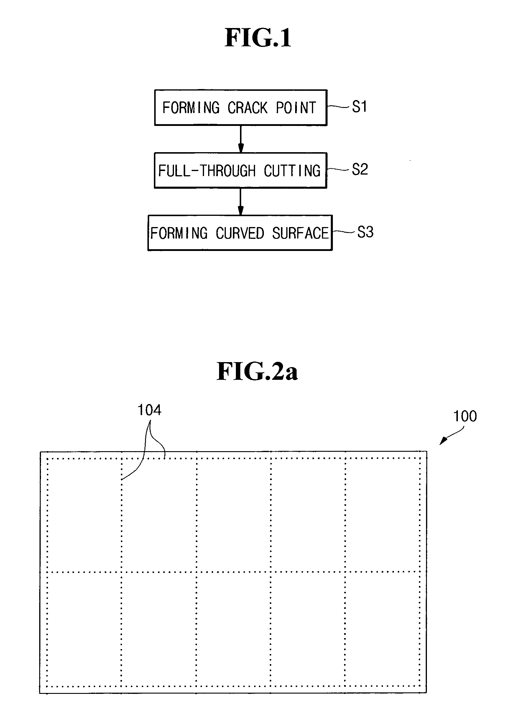
[0032]Referring to FIG. 1, a glass cutting method according to the present invention is illustrated by a flowchart.

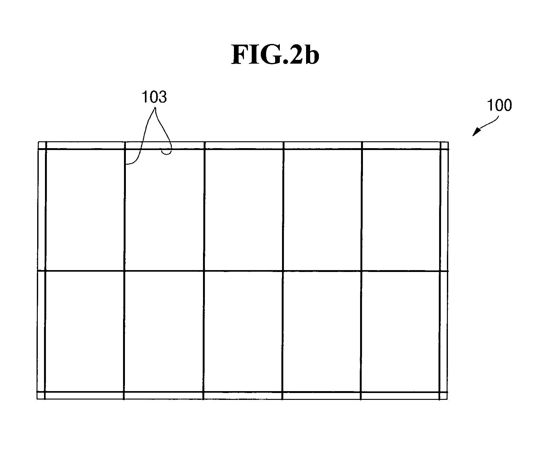
[0033]The glass cutting method according to the present invention includes forming a crack region S1 and a full-through cutting S2. Additionally, either a curved surface or a chamfer is formed along the cutting edge S3.

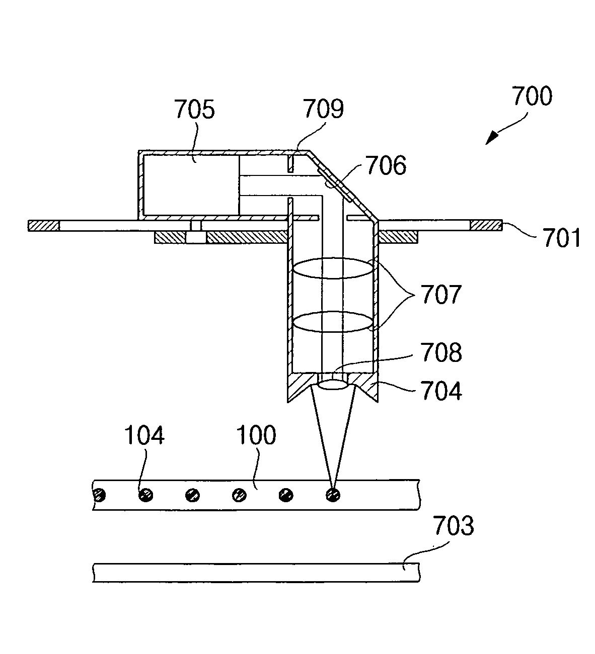
[0034]In forming the crack region S1, laser beams are output intermittently from a laser apparatus capable of moving in any X, Y and Z direction, so that crack regions with a constant size are formed at set pitches inside flat glass. For instance, as shown in FIG. 2a, the glass 100 is loaded and the crack regions 104 are then preformed inside the glass 100 along the cutting edge by outputting laser beams intermittently.

[0035]Here, it is desirable that the crack region 104 is formed in a size of approximately 1-20 μm. When the size of the crack region 104 is approximately 1 μm or less, the full-through laser cutting process may not be performed properly du...


PUM

PropertyMeasurementUnit
Fractionaaaaaaaaaa
Lengthaaaaaaaaaa
Sizeaaaaaaaaaa

Abstract

A glass cutting method and glass for a flat panel display. This glass cutting method forms crack regions of a constant size and pitch inside the glass using a laser and performs the full-through cutting process along the crack regions with a laser, thereby increasing cutting edge quality, shortening the cutting time and reducing the production cost.

Description

CLAIM OF PRIORITY[0001]This application makes reference to, incorporates the same herein, and claims all benefits accruing under 35 U.S.C. §119 from an application earlier filed in the Korean Intellectual Property Office on 7 Aug. 2007 and there duly assigned Serial No. 10-2007-0078951.BACKGROUND OF THE INVENTION[0002]1. Field of the Invention[0003]The present invention relates to glass cutting method, glass for flat panel display thereof and flat panel display device using it.[0004]2. Description of the Related Art[0005]A plasma display device, for instance, forms a barrier rib and a phosphor layer between two thin substrates and injects an inert gas. Then, a high voltage is applied to the inert gas. As a result thereof, ultra-violet rays are emitted from an inert gas so as to excite the phosphor layer and the excited phosphor layer emits a visible ray.[0006]Further, an organic light-emitting display device sequentially forms a semiconductor layer and an organic light-emitting laye...

Claims


Application Information

Patent Timeline
IPC IPC(8): G02B5/00B23K26/38
CPCB23K26/0604B23K26/0876B23K26/38G02F1/1303B23K26/421C03B33/0222B23K26/4075B23K26/60B23K26/40B23K2103/50
Inventor KIM, JINNAMCHOI, JUNGHYUCKHAN, GYOOWAN
Owner SAMSUNG SDI CO LTD
Why Eureka
Try Eureka