Network element and an infrastructure for a network risk management system

a network risk management and network element technology, applied in the field of network risk management, can solve the problems of affecting the safety of communication, and difficult for network administrators to supervise internal traffi

a network risk management and network element technology, applied in the field of network risk management, can solve the problems of affecting the safety of communication, and difficult for network administrators to supervise internal traffi

US20090044270A1Inactive Publication Date: 2009-02-12SHELLY ASAF +1

Image

  • Network element and an infrastructure for a network risk management system
  • Network element and an infrastructure for a network risk management system
  • Network element and an infrastructure for a network risk management system

Examples


Embodiment Construction

[0057]The principles and operation of a method and an apparatus according to the present invention may be better understood with reference to the drawings and the accompanying description, it being understood that these drawings are given for illustrative purposes only and are not meant to be limiting.

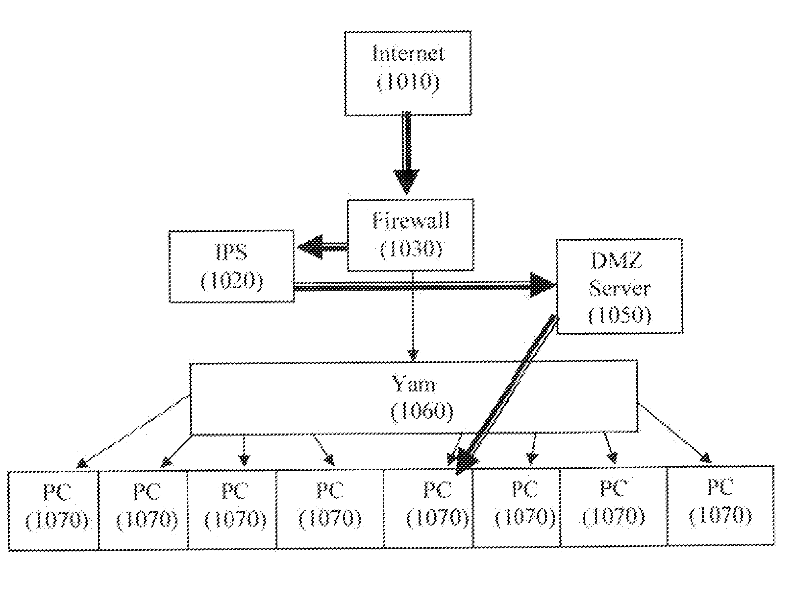
[0058]The solution provided by the present invention is a Network Risk Management system (NRM). NRM allows better network management, better security and a network topology that is less bound to the physical limitations.

[0059]The network topology of the present invention is based on a virtual network element that takes over the roles of existing network elements such as Switch, Router and possibly Firewall, IPS, etc.

[0060]The virtual network is comprised of physical elements that work together to form the network's infrastructure. The network topology can be configured using an external management element.

[0061]Each network element is called a Gal. The entire system is called a Yam.

[00...


PUM


Abstract

A system for a communication infrastructure in a network including at least one connected system (CS) and at least one network risk management network element (SW), wherein the network acts as a virtual network comprising at least one virtual network element, and wherein the at least one virtual network element takes over the roles of existing network elements comprising at least one of a switch, a router, a firewall and an intrusion prevention system (IPS), and wherein the virtual network is comprised of physical elements that work together to form the network's infrastructure.

Description

RELATED APPLICATIONS[0001]Cross-reference is made to co-pending provisional patent application number Ser. No. 10 / ______, titled “Software for a Realtime Infrastructure,” filed Jul. 10, 2007, for which the present application is a continuation-in-part and which is incorporated herein by reference and. Cross-reference is also made to co-pending provisional patent application number Ser. No. 10 / ______, titled “Advanced Processor Technology,” also filed Jul. 10, 2007, which again is incorporated herein by reference.FIELD OF THE INVENTION[0002]The present invention relates generally to network risk management, and more particularly, the invention relates to a network element and an infrastructure for a network risk management system.BACKGROUND OF THE INVENTION[0003]The common network open system interconnection (OSI) model has the following 7 layers:[0004]Layer 1. Physical layer[0005]Layer 2. Data Link layer[0006]Layer 3. Network layer[0007]Layer 4. Transport layer[0008]Layer 5. Session...

Claims


Application Information

Patent Timeline
12 Feb 2009
Publication
US20090044270A1
IPC
G06F15/18
CPC
H04L63/14; H04L63/02
Inventors
SHELLY, ASAF; FELDMAN, MOSHE