Solar cell and solar cell module

a solar cell and solar cell technology, applied in the direction of pv power plants, non-conductive materials with dispersed conductive materials, radiation control devices, etc., can solve the problems of increasing contact resistance, solar cell modules are particularly susceptible to temperature change, and the environment is susceptible to change, so as to reduce stress and weaker the adhesion of thermosetting resins

Active Publication Date: 2009-02-19
SANYO ELECTRIC CO LTD
View PDF2 Cites 16 Cited by
  • Summary
  • Abstract
  • Description
  • Claims
  • Application Information

AI Technical Summary

Benefits of technology

[0040]Therefore, according to the present embodiment, the sea-island structure is formed in a larger volume in the first layer 601 than in the second layer 602. This results in a weaker adhesion of the thermosetting resins than in the second layer 602. As a result, the present invention brings about an effect of reducing stress between the transparent conductive film 5 and the tabs 12 each in which internal stress is accumulated over a long-time use of the solar cell module.
[0041]Next, description will be provided concretely for the effects of the present invention.
[0042]Descriptions will be provided hereinbelow for a result of examination on effects of the second resin according to the present invention on the internal stress in the electrode.
[0043]First of all, an i type amorphous silicon layer with a thickness of 50 Å, a p type amorphous silicon layer with a thickness of 50 Å and an ITO film with a thickness of 50 Å were sequentially formed on the front surface of an n type single-crystal silicon substrate having a texture surface. Subsequently, an electrode with a thickness of 10 μm and an electrode with a thickness of 50 μm were formed, on the respective ITO films, of an conductive resin paste containing: a bisphenol A epoxy resin as the first resin according to the present invention; and a silicone resin as the second resin according to the present invention, which formed a sea-island structure between the second resin and the first resin. Note that, as the conductive filler, 50 wt % of globular silver powder with a particle size of 1 μmØ to 5 μmØ and 50 wt % of flaked silver powder with a particle size of 5 μmØ to 20 μmØ were contained in the conductive paste.
[0044]Thereafter, the internal stresses in the electrodes in the samples in which the electrodes were formed were examined, respectively, in the following manner by changing the concentration of the silicone resin in the conductive paste between 0 wt % to 20 wt % inclusive.
[0045]The acoustoelastic method and the like are known as a method of precisely measuring internal stress. Here, however, for the purpose of examining the internal stress on the surface of each silicon substrate in which a concave-convex texture surface was formed, a lattice pattern cutting method (in compliance with JIS K 5400) was used to examine the tab separation status. Thereby, the internal stress in the electrode was evaluated.

Problems solved by technology

In general, a solar cell module is set up outdoor, for example, on the roof of a house, and continues to be used for a long time and, therefore is susceptible to change in the environment, such as temperature change and humidity change.
The solar cell module is susceptible particularly to temperature change, because the solar cell module is configured by various members having different thermal expansion coefficients.
This is likely to cause a problem such as an increase of contact resistance between the solar cells and the corresponding tabs, or separation of a tab.

Method used


Image

  • Solar cell and solar cell module
  • Solar cell and solar cell module
  • Solar cell and solar cell module

Examples


first embodiment

[0025]Descriptions will be provided hereinafter for a first embodiment of the present invention by referring to the drawings.

1>

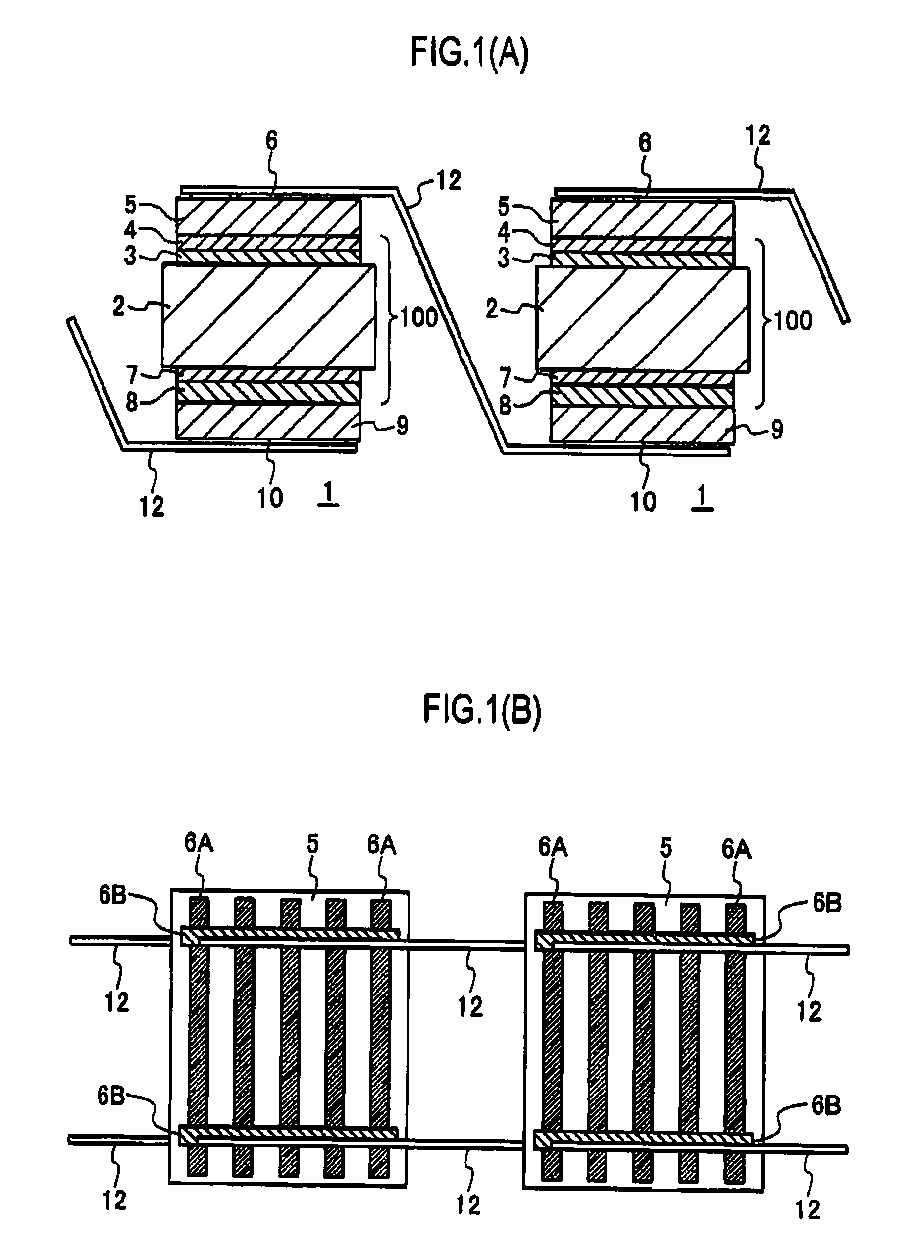
[0026]FIG. 1 is a structural drawing for showing a solar cell 1 according to the present embodiment. FIG. 1(A) is a cross-sectional structural drawing. FIG. 1(B) is a plan view viewed from the light-incidence side. Note that FIG. 1(A) is the cross-sectional structural drawing of the solar cell 1 taken in the longitudinal direction of a bus bar 6B shown in FIG. 1(B).

[0027]The solar cell 1 shown in FIG. 1 is an example of a solar cell having amorphous semiconductor layers in its connecting surfaces to which tabs 12 are bonded, respectively.

[0028]A substantially-intrinsic semiconductor (i type) amorphous silicon layer 3 and a p type amorphous silicon layer 4 are sequentially stacked on a principal surface of an n type single-crystal silicon substrate 2. In addition, a substantially-intrinsic semiconductor (i type) amorphous silicon layer 7 and an n type amorpho...

second embodiment

[0076]Descriptions will be provided hereinafter for a second embodiment of the present invention by referring to the drawings.

1>

[0077]The structure of the solar cell 1 and the solar cell module according to the present embodiment are the same as the structure of the solar cell 1 and the solar cell module according to the first embodiment. For this reason, descriptions will be omitted.

6>

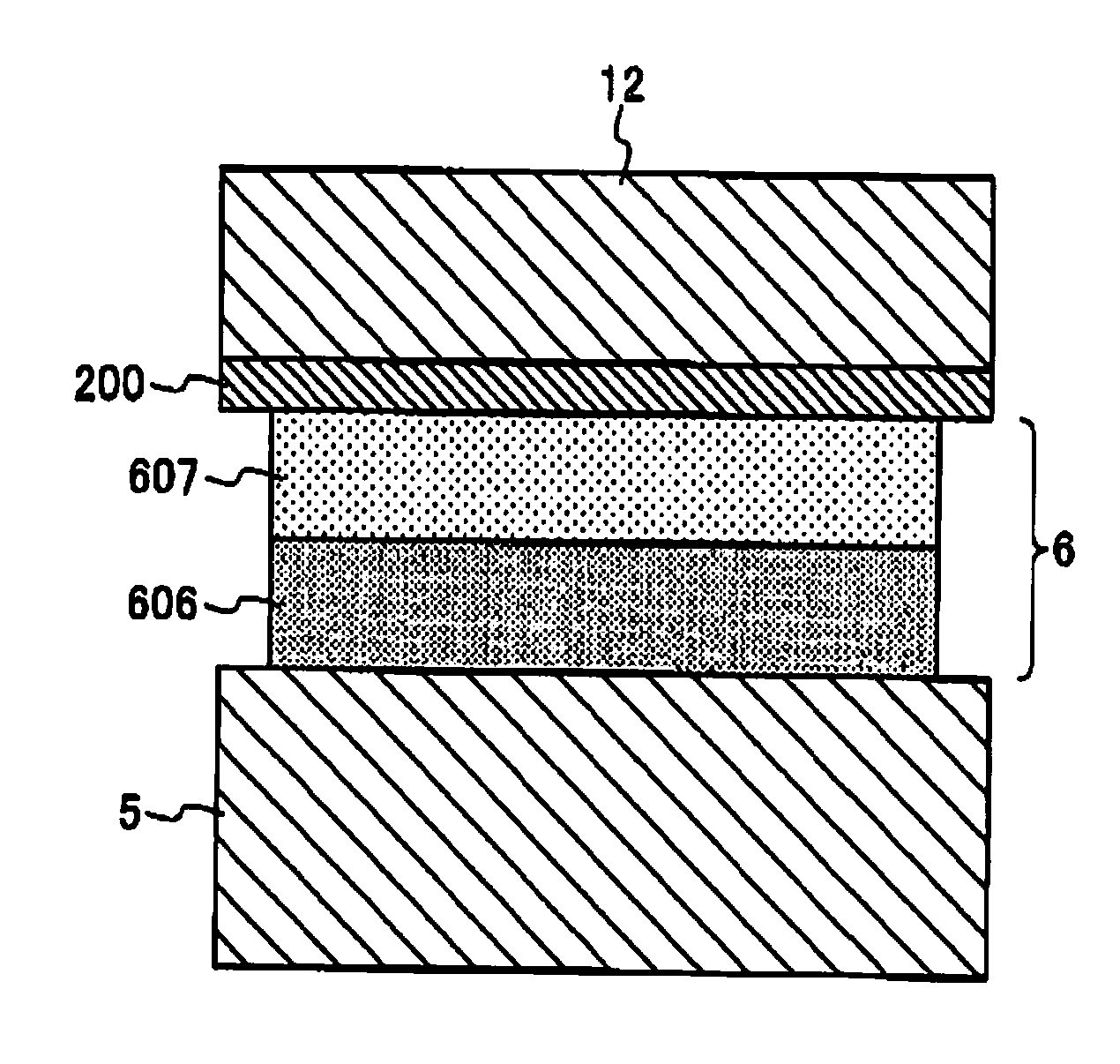
[0078]Next, detailed descriptions will be provided for a structure of the collector electrode 6 which is a characteristic part of the present invention. FIG. 6 is a magnified cross-sectional structural drawing for explaining the structure of the collector electrode which is arranged on the light-incidence side.

[0079]As shown in the drawing, the collector electrode 6 according to the present embodiment having a two-layer structure including: a first layer 606 arranged on the side in contact with the transparent conductive film 5; and a second layer 607 arranged on the side in contact with an solder lay...


PUM

PropertyMeasurementUnit
thicknessaaaaaaaaaa
thicknessaaaaaaaaaa
particle sizeaaaaaaaaaa

Abstract

A solar cell according to the present invention includes: a photoelectric conversion part having a photoelectric converting function; and a collector electrode provided at a side of a light-receiving surface of the photoelectric conversion part in a way that parts of the light-receiving surface are exposed. Interconnection tabs are connected at a side of a light-receiving surface of the collector electrode with an adhesive being interposed in between. The collector electrode contains a thermosetting first resin, an conductive material and a second resin for forming a sea-island structure between the second resin and the first resin. The collector electrode includes an internal region in the inside, a concentration ratio of the second resin to the first resin being higher in the internal region than in the surface region at the side of either the adhesive or the photoelectric conversion part.

Description

TECHNICAL FIELD[0001]The present invention relates to a solar cell and a solar cell module, and particularly to a technology for enhancing the yields and reliability.BACKGROUND ART[0002]A solar cell directly converts light emitted from the Sun as a source of clean and inexhaustibly-supplied energy to electricity and, therefore is expected as a new energy source.[0003]Each of such solar cells outputs electric power of only several watts. For this reason, in a case where solar cells are to be used as a source of electric power for a house, a building or the like, those solar cells are generally used in solar cell module including multiple solar cells electrically connected one to another in series or in parallel by conductive connecting members termed as tabs.[0004]In general, tabs are connected to a collector electrode provided beforehand on a connecting surface of a solar cell by soldering. In a case where the material constituting the connecting surface of the solar cell is made up...

Claims


Application Information

Patent Timeline
Patent Type & Authority Applications(United States)
IPC IPC(8): H01L31/042H01L31/00
CPCH01B1/22H01L31/022425H01L31/0376H01L31/0512Y02E10/52H01L31/0747H01L31/048Y02E10/50H01L31/04
Inventor YOSHIMINE, YUKIHIROTAIRA, SHIGEHARUTSUNOMURA, YASUFUMI
Owner SANYO ELECTRIC CO LTD
Why Eureka
Try Eureka