Method of and apparatus for laminated substrate assembly

a technology of laminated substrates and manufacturing methods, applied in photomechanical equipment, circuit masks, instruments, etc., can solve the problems of inability to reliably peel off base films from substrates, inability to accurately control the temperature of dry resist film cut strips, and inability to smooth the surface to be peeled off of base films. , to achieve the effect of efficient manufacturing of high-quality laminated substrate assemblies and simple process and arrangemen

Inactive Publication Date: 2009-02-19
FUJIFILM CORP
View PDF11 Cites 6 Cited by
  • Summary
  • Abstract
  • Description
  • Claims
  • Application Information

AI Technical Summary

Benefits of technology

[0009]It is a major object of the present invention to provide a method of and an apparatus for manufacturing a high quality la

Problems solved by technology

However, the temperature of the cut strip of the dry resist film 4 cannot accurately be controlled by the heat from the substrates 1 that are heated by the heating rollers 9.
Consequently, if the base film is to be removed from the substrates 1, leaving desired resist layers thereon, the base f

Method used


Image

  • Method of and apparatus for laminated substrate assembly
  • Method of and apparatus for laminated substrate assembly
  • Method of and apparatus for laminated substrate assembly

Examples


first embodiment

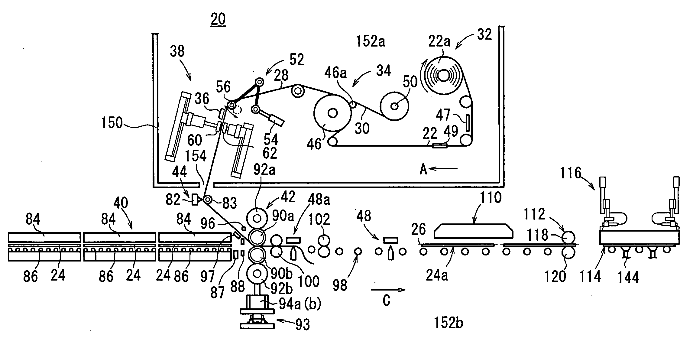
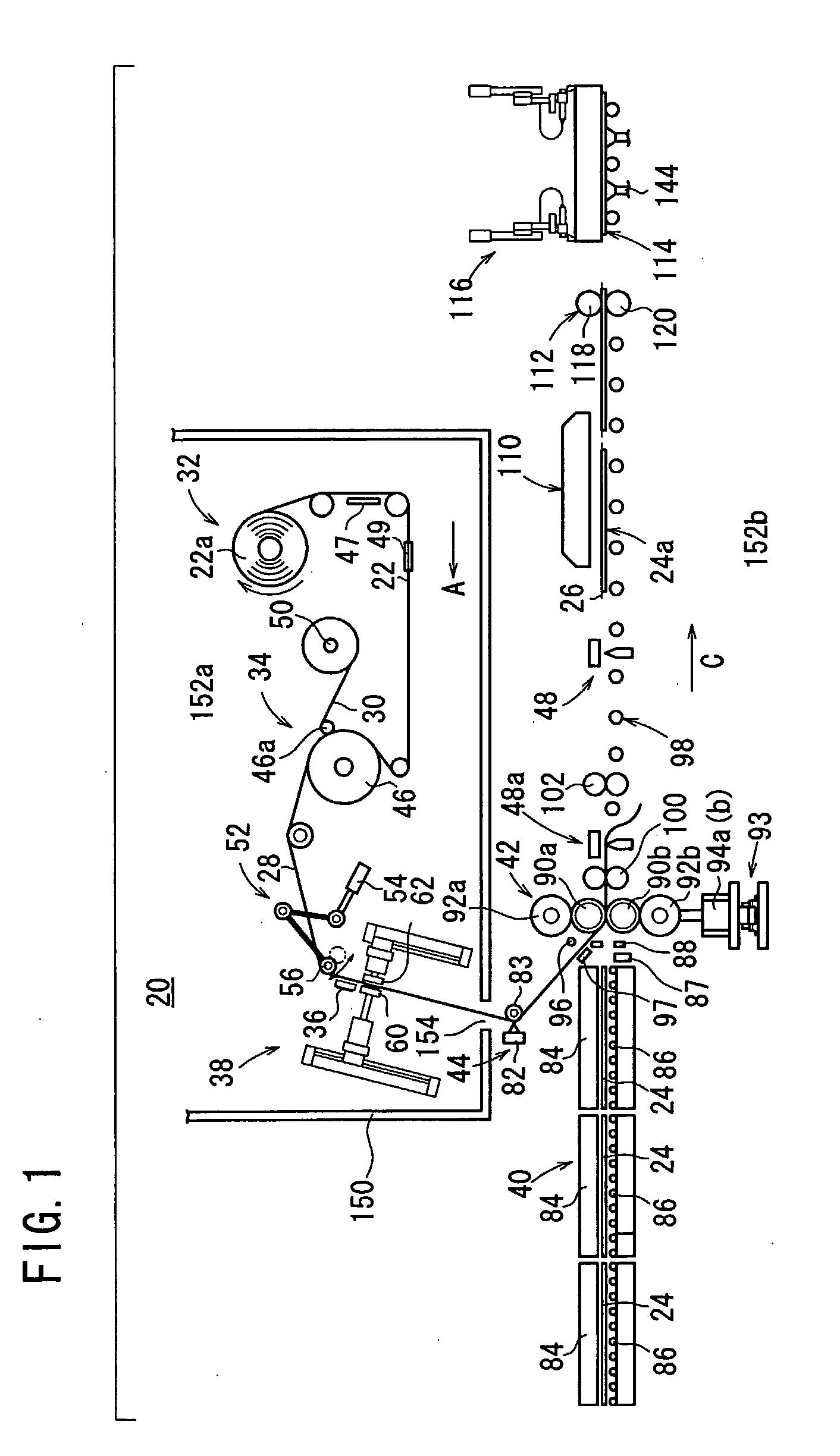
[0035]FIG. 1 shows in schematic side elevation an apparatus 20 for manufacturing a photosensitive laminated body (laminated substrate assembly) according to the present invention. The manufacturing apparatus 20 operates to thermally transfer a photosensitive resin layer 29 (described later) of an elongate photosensitive web 22 to glass substrates 24 in a process of manufacturing printed wiring boards, liquid crystal panels, PDPs, or color filters for use with organic EL panels.

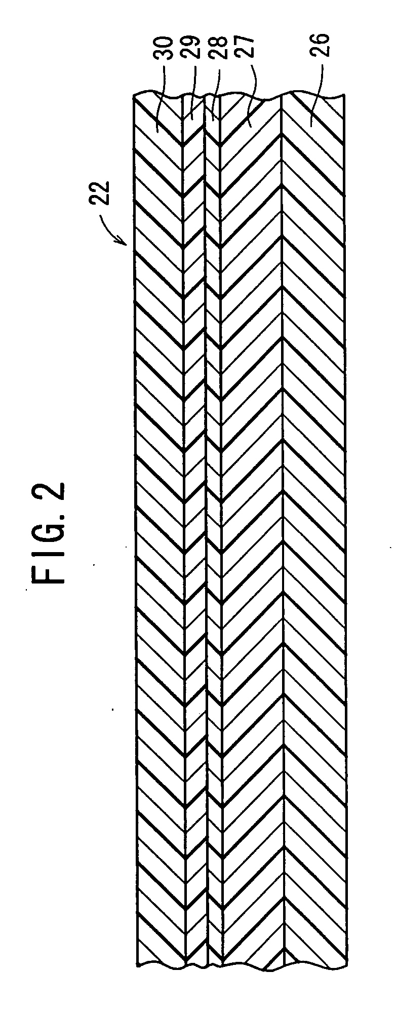
[0036]FIG. 2 shows in cross section the photosensitive web (laminated body) 22 that is employed in the manufacturing apparatus 20. The photosensitive web 22 comprises a laminated assembly of a flexible base film (support layer) 26, a cushion layer (thermoplastic resin layer) 27 disposed on the base film 26, an intermediate layer (oxygen blocking film) 28 disposed on the cushion layer 27, a photosensitive resin layer 29 disposed on the intermediate layer 28, and a protective film 30 disposed on the photosensiti...

second embodiment

[0106] the joined substrate 24a to which the photosensitive web 22 is laminated by the joining mechanism 42 is delivered to the prepeeler 204 which pre-peels off the base film 26. Thereafter, the joined substrate 24a is sent to the peeling mechanism 202. In the peeling mechanism 202, the takeup shaft 208 is rotated to continuously wind the base film 26 and the masking tape 36 from the joined substrate 24a. After the photosensitive web 22 is cut off in case of trouble and separated to discharge defective sections, the leading end of the base film 26 on a joined substrate 24a to which the photosensitive web 22 starts being laminated and the trailing end of the base film 26 wound on the takeup shaft 208 are automatically joined to each other by the automatic joining unit 210.

[0107]The photosensitive laminated body 114 from which the base film 26 and the masking tape 36 are peeled off is placed in an inspecting station combined with the measuring unit 218. In the inspecting station, the...

third embodiment

[0113]FIG. 15 schematically shows in side elevation a heating mechanism 230 of a manufacturing apparatus according to the present invention.

[0114]As shown in FIG. 15, the heating mechanism 230 has a heater 232 for heating the joined substrate 24a from the side of the base film 26 out of contact therewith. The heater 232 is covered with a cover 234. The heater 232 may comprise an infrared bar header, a halogen heater, a carbon heater, a ceramics type heater, or a coil heater. Alternatively, the heater 232 may comprise a plate heater or a ceramics heater having an angularly displaceable or swinging mechanism, or a plurality of light lamps for emitting light which does not contain light components in a wavelength range to which the photosensitive web 22 is sensitive.


PUM

PropertyMeasurementUnit
Temperatureaaaaaaaaaa

Abstract

A manufacturing apparatus has a joining mechanism for bonding a photosensitive web to a glass substrate such that a cushion layer thereof faces the glass substrate, thereby to produce a joined substrate. The manufacturing apparatus also has a cooling mechanism for forcibly cooling the joined substrate with cooling air, a heating mechanism for heating the cushion layer to a temperature in a predetermined temperature range up to a glass transition temperature thereof, and a peeling mechanism for peeling off a base film of the photosensitive web from the heated joined substrate. The cooling mechanism, the heating mechanism, and the peeling mechanism are successively arranged in the direction in which the joined substrate is fed along.

Description

TECHNICAL FIELD[0001]The present invention relates to a method of and an apparatus for manufacturing a laminated substrate assembly by bonding a laminated body including a support layer and at least one resin layer laminated thereon, to a substrate such that the resin layer faces the substrate, and thereafter peeling off the support layer from the resin layer.BACKGROUND ART[0002]Substrates for liquid crystal panels, substrates for printed wiring boards, and substrates for PDP panels, for example, have a photosensitive sheet (photosensitive web) having a photosensitive material (photosensitive resin) layer and applied to substrate surfaces. The photosensitive sheet comprises a photosensitive material layer and a protective film that are successively deposited on a flexible plastic support.[0003]An applying apparatus for applying such a photosensitive sheet usually operates to feed substrates such as glass substrates, resin substrates, or the like at spaced intervals, peel off the pro...

Claims


Application Information

Patent Timeline
IPC IPC(8): B32B38/10B32B37/04B44C1/17G03F7/16B29C65/02B29L9/00B32B37/00H05K3/28
CPCB32B38/10H05K3/0079G03F7/161B44C1/17
Inventor SUEHARA, KAZUYOSHIWATANABE, YASUHISAARIMITSU, HARUHITOGOTOH, HIDENORI
Owner FUJIFILM CORP
Why Eureka
Try Eureka