Mower payload bin and support structure

a payload bin and mower technology, applied in the field of lawn mower accessories, can solve the problems of consumers foregoing the increased maneuverability of a zero-turn mower, the inability of zero-turn mowers to adapt to consumers, and the inability of zero-turn mowers to tow trailers or other payload bins, etc., to achieve efficient accept and transport payload, improve flexibility and practicality of zero-turn mowers, and stable coupling

Inactive Publication Date: 2009-02-19
K B MOWERS
View PDF1 Cites 9 Cited by
  • Summary
  • Abstract
  • Description
  • Claims
  • Application Information

AI Technical Summary

Benefits of technology

[0012]Accordingly, the present invention provides a zero-turn mower accessory that improves the flexibility and practicality of zero-turn mowers by allowing such mowers to efficiently accept and transport a payload of earth, mulch, or other materials. In particular, the accessory is stably coupled to and operable with a zero-turn lawn mower. The accessory provides a robust and durable payload bin assembly that is capable of routinely supporting significant payloads weighing in excess of several hundred pounds. Finally, the accessory is readily adaptable for attachment to a variety of zero-turn and non-zero-turn mower configurations.

Problems solved by technology

However, zero-turn mowers are generally not adaptable to assist consumers in other lawn care endeavors.
For example, zero-turn mowers are not typically desirable for towing trailers or other payload bins.
This fact often forces consumers to forego the increased maneuverability of a zero-turn mower in favor of the flexibility and practicality of conventional, less-maneuverable, riding lawn mowers.
Alternatively, consumers wishing to achieve the dual goals of high maneuverability and acceptable towing capacity may be forced to undertake the prohibitive expense of using two pieces of expensive machinery for each goal, namely, a zero-turn mower for mowing and a conventional mower for hauling.

Method used


Image

  • Mower payload bin and support structure
  • Mower payload bin and support structure
  • Mower payload bin and support structure

Examples


Embodiment Construction

[0027]The present invention now will be described more fully hereinafter with reference to the accompanying drawings, in which some, but not all embodiments of the invention are shown. Indeed, this invention may be embodied in many different forms and should not be construed as limited to the embodiments set forth herein; rather, these embodiments are provided so that this disclosure will satisfy applicable legal requirements. Like numbers refer to like elements throughout.

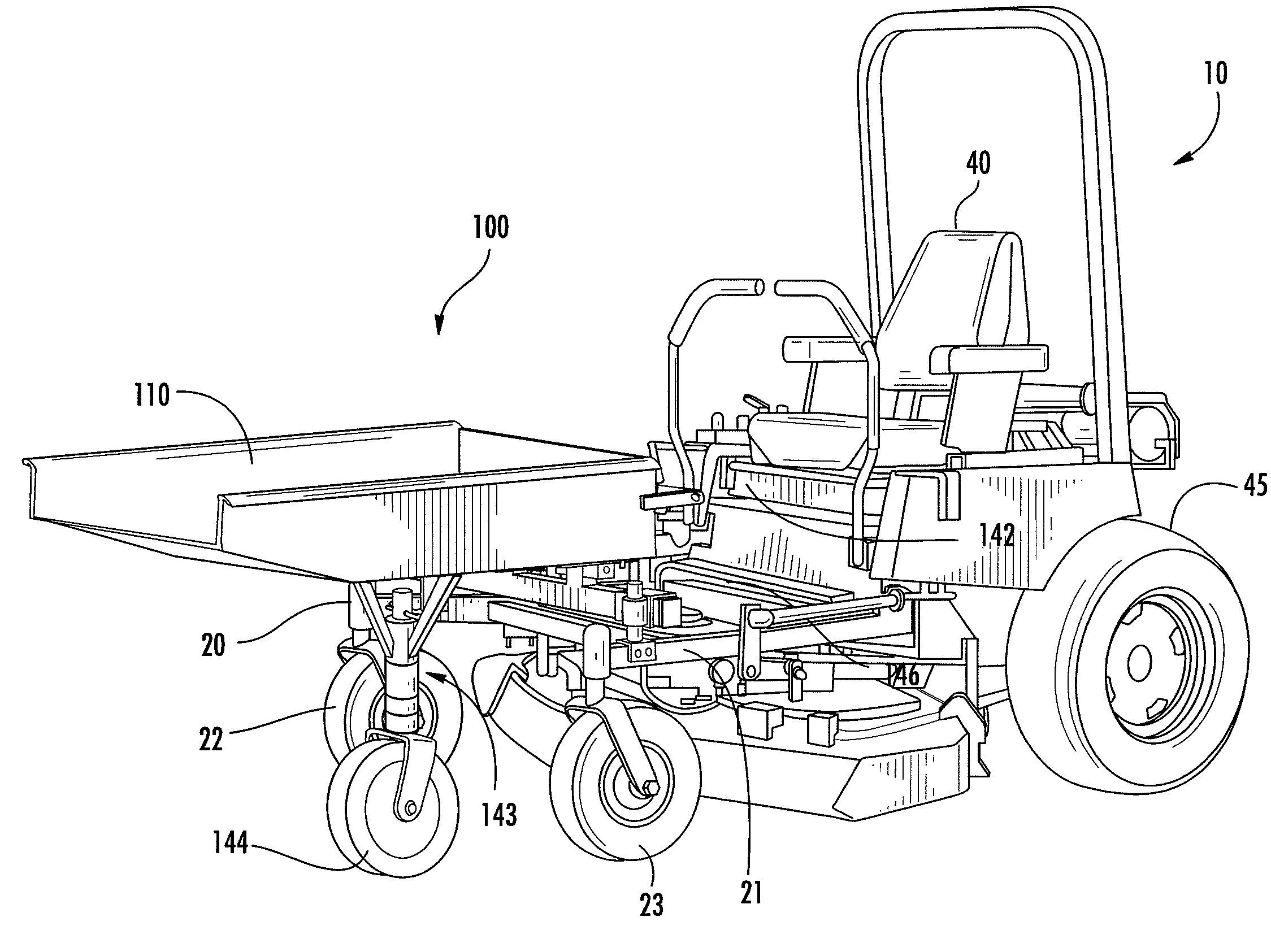
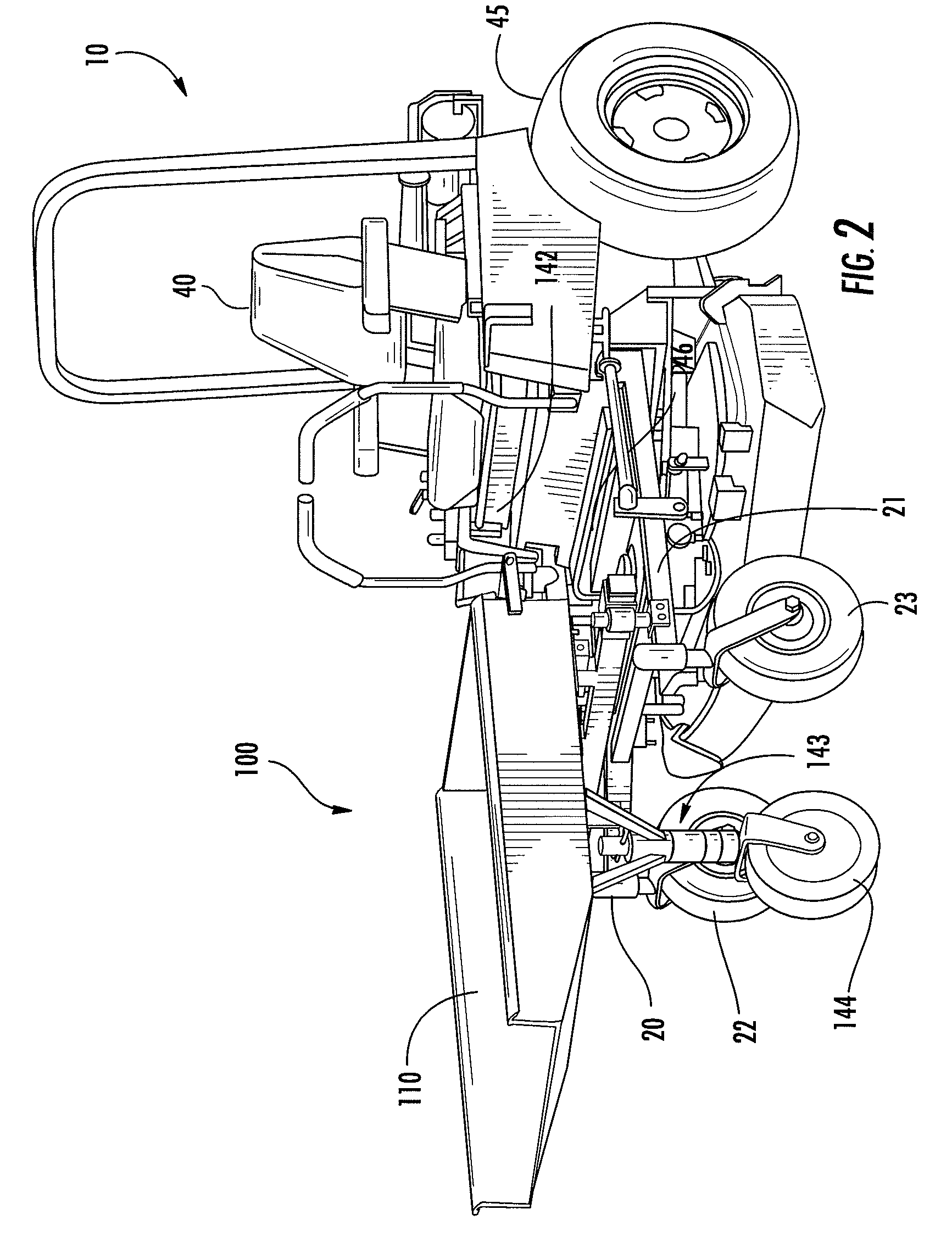
[0028]Referring to FIGS. 2 and 3, there is illustrated a payload bin assembly 100 coupled to a zero-turn mower 10 in accordance with one embodiment of the present invention. In the depicted embodiment, the payload bin assembly 100 is comprised of a payload bin 110, a wheel-based support assembly 140, and a mower-based support assembly 150. The payload bin 110 is structured to accept, transport, and dump payloads of earth, mulch, and other materials. The payload bin 110 is pivotally supported by a payload support f...


PUM


Abstract

The present invention is directed to a payload bin assembly that is stably coupled to zero-turn and non-zero-turn mowers alike. In various embodiments, the payload bin assembly is comprised of a durable payload support frame having a first end and a second end. A payload bin is pivotally coupled proximate the first end of the payload support frame. The payload support frame is supported at its first and second ends by a wheel-based support assembly and a mower-based support assembly, respectively.

Description

CROSS-REFERENCE TO RELATED APPLICATIONS[0001]The present application is a continuation-in-part to U.S. patent application Ser. No. 11 / 067,658 entitled MOWER PAYLOAD BIN, which was filed Feb. 2, 2005; the contents of which are incorporated herein in their entirety.BACKGROUND OF THE INVENTION[0002]1. Field of the Invention[0003]This invention relates generally to lawn mower accessories and, more particularly to a front-mounted payload bin for a zero-turn lawn mower.[0004]2. Description of the Related Art[0005]The design and operation of commercial and residential lawn mowers has changed considerably over the years. Early spinning wheel push-mowers have evolved into the extremely maneuverable, self-powered, high-horse power riding mowers of today. Perhaps the most maneuverable of modern lawn mowers is the “zero-turn” mower depicted in FIG. 1. Zero-turn mowers 10 include a maneuverable rear wheel drive system that accommodates “transmission steering,” that is, the mower turns by control...

Claims


Application Information

Patent Timeline
Patent Type & Authority Applications(United States)
IPC IPC(8): B60P1/24
CPCA01D43/00B60Y2200/223B60B33/0005B60B33/0015B60B33/0021B60B33/0039B60B33/0049B60B33/0057B60B33/0068B60B33/0073B60B33/04B60B35/04B60B35/06B60P1/283B60B33/0002
Inventor BROOKS, KENNY M.
Owner K B MOWERS
Why Eureka
Try Eureka