Inter-helix inductor devices

Inactive Publication Date: 2009-02-19
IND TECH RES INST
23 Cites 21 Cited by

AI-Extracted Technical Summary

Problems solved by technology

This can severely affect characteristics and performance of a circuit and a system module.
Moreover, distribution of electromagnetic field can also affect the quality factor of the inductor device.
Surface roughness and process variations can also affect the quality factor of the inductor device.
On the other hand, when designing two-port inductor devices, circuit layout complexity become perplexed due to a far distance between input end and output end.
Moreover, since complexity of advanced communication system is continuing to increase, more inductor devices are needed...

Benefits of technology

[0015]The invention provides a three-dimensional inter-helix spiral inductor structure. Circuit layout problems due to far distance between the first terminal and the second terminal of the conventional two-port inductor device can be effectively solved. The inductor device can facilita...

Abstract

The invention is directed to inter-helix inductor devices. The inter-helix inductor device includes a dielectric substrate. An input end is disposed on the first surface of the dielectric substrate. A clockwise winding coil has one end connecting to the input end and at least one winding turn through the dielectric substrate. A counter clockwise winding coil includes at least one winding turn through the dielectric substrate, wherein the clockwise and counter clockwise winding coils are connected by an interconnection. An output end is disposed on the dielectric substrate, connects one end of the counter clockwise winding coil, and is adjacent to the input end.

Application Domain

Transformers/inductances coils/windings/connectionsPrinted inductances +1

Technology Topic

InductorDielectric substrate +5

Image

  • Inter-helix inductor devices
  • Inter-helix inductor devices
  • Inter-helix inductor devices

Examples

  • Experimental program(1)

Example

[0032]It is to be understood that the following disclosure provides many different embodiments, or examples, for implementing different features of various embodiments. Specific examples of components and arrangements are described below to simplify the present disclosure. These are merely examples and are not intended to be limiting. In addition, the present disclosure may repeat reference numerals and/or letters in the various examples. This repetition is for the purpose of simplicity and clarity and does not in itself indicate a relationship between the various embodiments and/or configurations discussed. Moreover, the formation of a first feature over or on a second feature in the description that follows may include embodiments in which the first and second features are formed in direct contact or not in direct contact.
[0033]FIG. 4 is a plan view of a spiral inductor structure. A spiral inductor device 100 includes a first terminal 102 (e.g., an input end) connecting a spiral winding coil, and further connecting to a second terminal 108 (e.g., an output end). The spiral winding coil includes conductive segments 105a-105e and 107a-107d disposed on both sides of a dielectric substrate, respectively. Conductive segments 105a-105e and 107a-107d are connected by interconnections 104a-104e and 106a-106e, respectively, thereby creating a clockwise winding spiral coil and a counter-clockwise winding spiral coil. The first terminal 102 (e.g., an input end) and the second terminal 108 (e.g., an output end) of the spiral inductor device 100 are respectively disposed on two sides of the spiral coil. If the spiral coil layout is arranged as a two-port inductor device, the input and output ends are disposed apart from each other, consuming lots of circuit layout area, thus hindering integration with other circuitry devices. Therefore, a desirable inter-helix inductor device should effectively reduce layout area requirement and achieve high quality factor characteristic. During operation, signals 100SF are fed in the first terminal 102 (e.g., an input end) passing through the spiral coil inductor, and is further transmitted to the second terminal 108 (e.g., an output end).
[0034]According to an embodiment of the invention, the spiral inductor device 100 uses crossed layout transmission lines disposed on different layers of substrate. Each transmission line is connected to each other by interconnections, thereby creating an embedded stereographic inter-helix inductor structure. The input and output ends of the two-port inter-helix inductor structure are arranged closer to each other, thereby effectively reducing circuit layout area requirement and providing more design margins for system circuit layout. Further, the embedded stereographic inductor can concentrate electromagnetic field distribution in the central region of the inter-helix spiral coil, thereby reducing electromagnetic radiation and energy loss and improving quality factor.
[0035]FIG. 5 is a plan view of an embodiment of a inter-helix spiral inductor structure of the invention. Referring to FIG. 5, an inter-helix spiral inductor device 200 includes dielectric substrates 300 as shown in FIG. 6, and a first terminal 202 (e.g., an input end) disposed on the dielectric substrates. A clockwise winding conductive coil connecting the first terminal 202 with at least one winding turn surrounds the dielectric substrates. The clockwise winding conductive coil includes conductive segments 205a, 205b and 207a, 207c disposed on both sides of the dielectric substrates, respectively. Conductive segments 205a, 205b and 207a, 207c are connected by first interconnections 204a, 204b and 206a, 206b, respectively.
[0036]A counter-clockwise winding conductive coil has at least one winding turn surrounding the dielectric substrates. The counter-clockwise winding conductive coil includes conductive segments 215a, 215b and 217a, 217b disposed on both sides of the dielectric substrates, respectively. Conductive segments 215a, 215b and 217a, 217b are connected by second interconnections 214a, 214b and 216a, 216b, respectively. The clockwise winding and counter-clockwise winding conductive coils are connected by a third interconnection 210. A second terminal 208 (e.g., an output end) connects the counter-clockwise winding conductive coil and is adjacent to the first terminal 202 (e.g., an input end). During operation, signals 200SF are fed in the first terminal 202 (e.g., an input end) passing sequentially through the clockwise winding conductive coil, the third interconnection 210, and the counter-clockwise winding conductive coil, and is further transmitted to the second terminal 208 (e.g., an output end). Since the transmission lines (conductive segments) are crossed over on the upper and lower layers of the dielectric substrate (i.e., the transmission lines can be disposed on different layers), the input and output signals can be transmitted on the same route. Note that the first terminal 202 (e.g., an input end) of the inter-helix inductor device is adjacent to the second terminal 208 (e.g., an output end) such that the circuit layout area can thus be reduced, thereby improving integration with other active and passive devices and providing more design margins for system circuit layout.
[0037]FIG. 6 is a schematic view of an embodiment of the dielectric substrate of the invention. A suitable dielectric substrate for embodiment of the invention comprises multi-layered substrates 300. The inter-helix spiral inductor 200 is embedded in the multi-layered substrates 300. For example, the multi-layered substrates 300 includes a first dielectric layer 310 (e.g., 4 mil RO4403 dielectric material), a second dielectric layer 320 (e.g., 2 mil high dielectric constant material HiDK 20), a third dielectric layer 330 (e.g., 12 mil BT), a fourth dielectric constant layer 340 (e.g., 2 mil HiDK 20), and a fifth dielectric layer 350 (e.g., 4 mil RO4403). The dielectric substrate comprises a polymer substrate, a ceramic substrate, or a semiconductor substrate, and the dielectric substrate can be made of a singular material or a composite-substrate made of multiple materials. Moreover, the dielectric substrate comprises a circuit with at least one active device or passive device.
[0038]FIG. 7A is stereographical view of an embodiment of the inter-helix inductor devices of the invention, and FIG. 7B is a plan view of the inter-helix inductor devices of FIG. 7A. Referring to FIG. 7A, the inter-helix inductor device 400 includes an inter-helix winding coil 420 embedded in the multi-layered dielectric substrates 410. A first terminal 430 (e.g., an input end) and a second terminal 440 (e.g., an output end) are disposed on the dielectric substrates 410. Ground lines 412 are disposed at the peripheral area of the inter-helix inductor device 400.
[0039]Note that according embodiments of the invention a cap layer can be optionally formed covering the dielectric substrates 410. Alternatively, a bottom layer can be optionally formed underlying the back of the dielectric substrates 410. More specifically, interconnections between different layers can be formed by different stacking hole processes comprising a through hole process, a blind hole process, or a buried hole process to complete the inter-helix inductor structure.
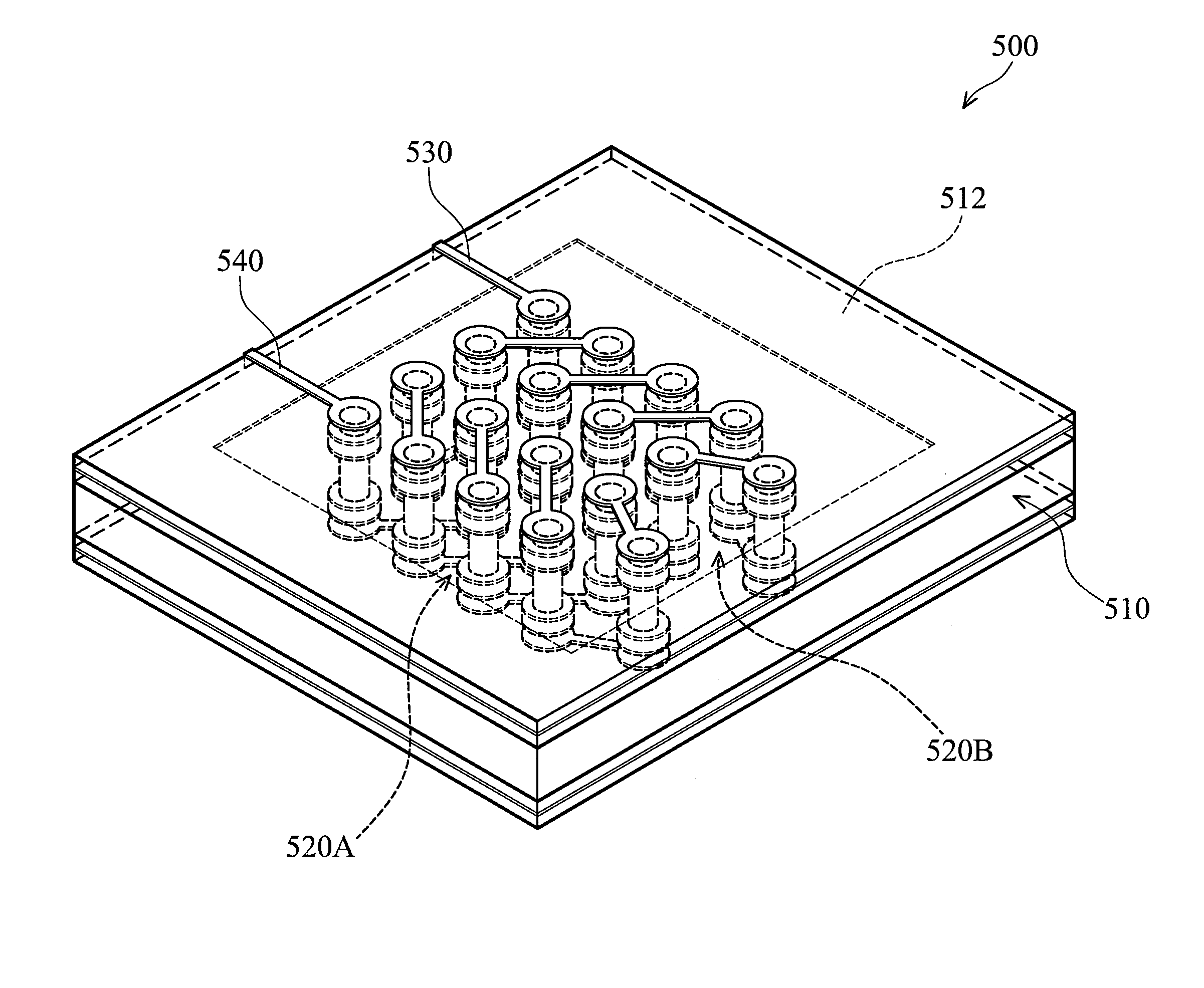
[0040]FIG. 8A is stereographical view of another embodiment of the double inter-helix inductor devices of the invention, and FIG. 8B is a plan view of the double inter-helix inductor devices of FIG. 8A. Referring to FIG. 8A, the double inter-helix inductor device 500 includes a first inter-helix winding coil 520B and a second inter-helix winding coil 520A embedded in the multi-layered dielectric substrates 510. The first and second inter-helix winding coils 520A and 520B are connected by an interconnection 525. A first terminal 530 (e.g., an input end) is connected to the first inter-helix winding coil 520A, and a second terminal 540 (e.g., an output end) is connected to the second inter-helix winding coil 520B. Both the first and second terminals 530 and 540 are disposed on the dielectric substrates 510. Ground lines (planes) 512 are disposed at the peripheral area of the double inter-helix inductor device 500.
[0041]FIG. 9A shows relationship between inductance and frequency of the inter-helix inductor device in accordance with embodiments of the invention, and FIG. 9B shows relationship between inductance and frequency of the double inter-helix inductor device in accordance with embodiments of the invention. Referring to FIGS. 9A and 9B, the inductance of the inter-helix inductor device 400 is about 5.16 nH at 45 MHz. On the contrary, the inductance of the double inter-helix inductor device 500 is about 10.28 nH at 45 MHz. Further, referring to FIGS. 10A and 10B, the maximum quality factor of the inter-helix inductor device 400 is about 57.54, while the maximum quality factor of the double inter-helix inductor device 500 is about 51.03. Therefore, the inductance of the inter-helix inductor device 500 can be double that of the single inter-helix inductor device without affecting the maximum quality factor.
[0042]While the invention has been described by way of example and in terms of the preferred embodiments, it is to be understood that the invention is not limited to the disclosed embodiments. To the contrary, it is intended to cover various modifications and similar arrangements (as would be apparent to those skilled in the art). Therefore, the scope of the appended claims should be accorded the broadest interpretation so as to encompass all such modifications and similar arrangements.

PUM

no PUM

Description & Claims & Application Information

We can also present the details of the Description, Claims and Application information to help users get a comprehensive understanding of the technical details of the patent, such as background art, summary of invention, brief description of drawings, description of embodiments, and other original content. On the other hand, users can also determine the specific scope of protection of the technology through the list of claims; as well as understand the changes in the life cycle of the technology with the presentation of the patent timeline. Login to view more.

Similar technology patents

Metal overall shielding double-conductor heating cable

InactiveCN102958213AHigh mechanical strengthReduce electromagnetic radiation
Owner:练高水

Magnetic core of electromagnetic oven

ActiveCN105161247AReduce electromagnetic radiationImprove heating efficiency
Owner:江苏佰迪凯磁性材料有限公司

Magnetic core applied to induction cooker

ActiveCN105157069AReduce electromagnetic radiationImprove heating efficiency
Owner:江苏佰迪凯磁性材料有限公司

Terminal processing method and device

InactiveCN105592200ADealing with High Radiation Intensity DamageReduce electromagnetic radiation
Owner:ZTE CORP

A power supply busbar for segmental power supply linear motor

ActiveCN114303471BReduce electromagnetic radiationReduce the impact
Owner:NAVAL UNIV OF ENG PLA

Classification and recommendation of technical efficacy words

  • reduce electromagnetic radiation

Optical module

ActiveCN106646778AReduce electromagnetic radiationImprove EMC performance
Owner:HISENSE BROADBAND MULTIMEDIA TECH

Wave-absorbing LED-lamp nylon heat-conduction composite and preparing method thereof

InactiveCN106046770AReduce electromagnetic radiationImprove thermal performance
Owner:BENGBU GAOHUA ELECTRONICS

Scratch-resistant seawater-corrosion-resistant degaussing cable and processing technology thereof

PendingCN110828033Aguaranteed performanceReduce electromagnetic radiation
Owner:中国船舶重工集团公司第七0四研究所

Low-radiation portable laser

ActiveCN106898936AReduce electromagnetic radiationImprove the quality of use
Owner:AZURE PHOTONICS

High-temperature graphene heating plate and preparation method thereof

ActiveCN109462900AHigh electrothermal conversion efficiencyReduce electromagnetic radiation
Owner:牛墨石墨烯应用科技有限公司
Why Eureka
Try Eureka