Impeller blade for centrifugal blower, blade-supporting rotator, impeller for centrifugal blower, and method for manufacturing impeller for centrifugal blower

a technology of centrifugal blower and impeller, which is applied in the direction of machines/engines, waterborne vessels, metal-working apparatuses, etc., can solve the problems of insufficient welding strength, large gaps between the weld surfaces of the members, and unevenness, so as to reduce the length of laser welded parts, reduce the pressure applied between the blade-supporting rotator and the blades, and achieve high welding strength

Inactive Publication Date: 2009-02-19
DAIKIN IND LTD
View PDF10 Cites 21 Cited by
  • Summary
  • Abstract
  • Description
  • Claims
  • Application Information

AI Technical Summary

Benefits of technology

[0043]With this method for manufacturing an impeller for a centrifugal blower, the blades, on which are formed blade weld surfaces inclined with respect to the rotator weld surfaces in a state in which the blade weld parts are disposed to face the rotator weld surfaces in the axial direction, are fixed by laser welding to the blade-supporting rotators in a state in which a load is applied so as to press the blade-supporting rotators and the blades each other in the axial direction. Therefore, it is possible to obtain an impeller for a centrifugal blower in which the blades are fixed to the blade-supporting rotators with high welding strength. Therefore, with this method for manufacturing an impeller for a centrifugal blower, when the blades are fixed by laser welding to the blade-supporting rotator, the pressure load applied between the blade-supporting rotator and the blades can be reduced, the length of the laser welded portions can be reduced, the blades can be given a complex rounded shape in order to improve blowing performance and noise quality, the blades can be thinned in order to reduce the weight of the impeller, and, as a result, costs can be reduced.

Problems solved by technology

If adherence between the weld surfaces of the members is insufficient and large gaps form between the weld surfaces, cases may arise in which sufficient welding strength is not achieved.
For example, in blades, end plates, or end rings molded from a resin, unevenness form to some degree in the weld surfaces of the members depending on the finishing precision during resin molding, and cases arise in which the gaps between the weld surfaces of the members become large depending on the unevenness, and sufficient welding strength is not achieved.
At this time, however, in cases in which the blades are thin or the blades have a complex rounded shape such that the axially central portions of the blades protrude in the radial direction of the impeller, the blades bend due to a load axially compressing the blades when the aforementioned pressure load is imposed, whereby cases arise in which large gaps form between the weld surfaces of the blades and the weld surface of the end plate, or between the weld surfaces of the blades and the weld surface of the end ring, and sufficient welding strength cannot be achieved.
Thus, in cases in which a structure is used in which resinous hollow blades are fixed by laser welding to a blade-supporting rotator such as a resinous end plate or a resinous end ring, it is difficult to achieve “adherence between the weld surfaces of the members,” which has a great affect on welding strength, and as a result, cases may arise in which sufficient welding strength is not achieved.

Method used


Image

  • Impeller blade for centrifugal blower, blade-supporting rotator, impeller for centrifugal blower, and method for manufacturing impeller for centrifugal blower
  • Impeller blade for centrifugal blower, blade-supporting rotator, impeller for centrifugal blower, and method for manufacturing impeller for centrifugal blower
  • Impeller blade for centrifugal blower, blade-supporting rotator, impeller for centrifugal blower, and method for manufacturing impeller for centrifugal blower

Examples


Embodiment Construction

[0090]The following is a description, made with reference to the drawings, of an embodiment of an impeller blade for a centrifugal blower, a blade-supporting rotator, an impeller for a centrifugal blower, and a method for manufacturing an impeller for a centrifugal blower according to the present invention.

[0091](1) Overall Configuration of Air Conditioning Apparatus

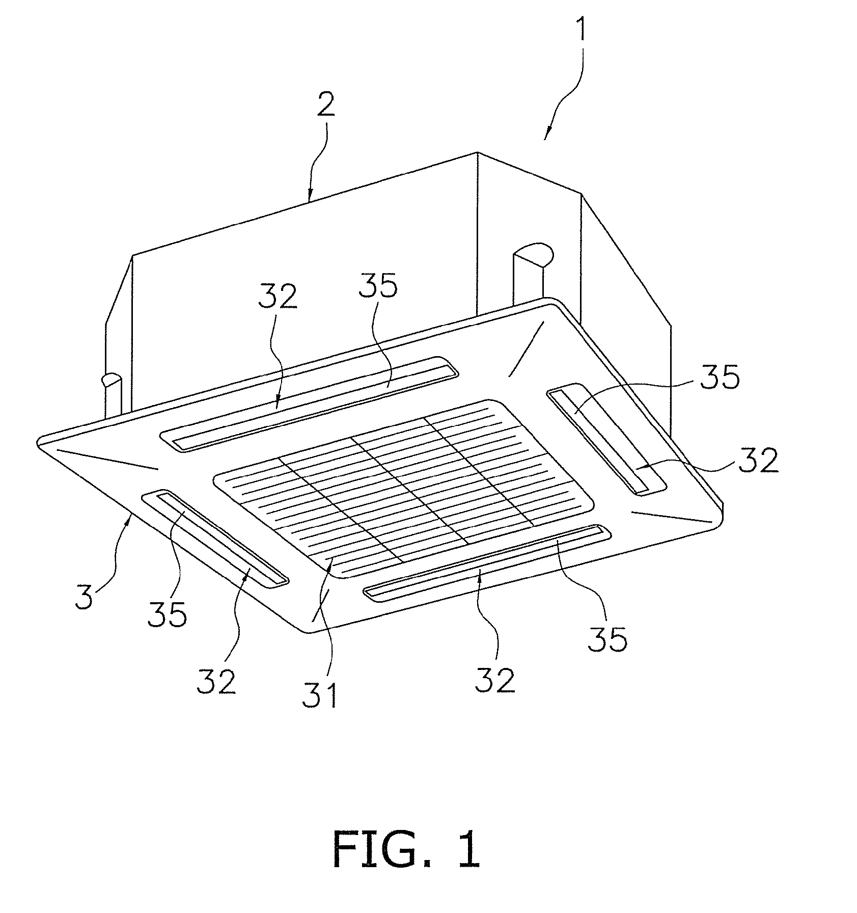
[0092]FIG. 1 shows an external perspective view of an air conditioning apparatus 1 comprising a centrifugal blower that uses a blade, a blade-supporting rotator, and an impeller for a centrifugal blower according to one embodiment of the present invention (the ceiling is omitted). The air conditioning apparatus 1 is a ceiling-embedded air conditioning apparatus, and comprises a casing 2 for accommodating various structural devices in its interior, and a face panel 3 disposed on the underside of the casing 2. Specifically, the casing 2 of the air conditioning apparatus 1 is disposed by being inserted into an opening forme...


PUM

PropertyMeasurementUnit
angleaaaaaaaaaa
anglesaaaaaaaaaa
angles of inclinationaaaaaaaaaa

Abstract

Blades of an impeller for a centrifugal blower are resinous hollow blades having hollow spaces formed in the blade interiors, and having first blade weld parts welded to plate weld surfaces of an end plate, wherein first blade weld surfaces inclined with respect to the plate weld surfaces are formed on the first blade weld parts in a state in which the first blade weld parts are disposed to face the plate weld surfaces in the axial direction.

Description

TECHNICAL FIELD[0001]The present invention relates to an impeller blade for a centrifugal blower, a blade-supporting rotator, an impeller for a centrifugal blower, and a method for manufacturing an impeller for a centrifugal blower. The present invention particularly relates to an impeller blade for a centrifugal blower, a blade-supporting rotator, an impeller for a centrifugal blower, and a method for manufacturing an impeller for a centrifugal blower wherein the centrifugal blower is configured by fixing resinous blades having hollow spaces formed in interiors thereof to a resinous blade-supporting rotator by laser welding.BACKGROUND ART[0002]Conventionally, turbofans, diagonal-flow fans, and other such centrifugal blowers have been used in ventilation apparatuses, air conditioning apparatuses, air purifiers, and the like. An impeller for this type of centrifugal blower comprises a resinous end plate rotated around a rotational axis by a motor or another such drive mechanism, a pl...

Claims


Application Information

Patent Timeline
Patent Type & Authority Applications(United States)
IPC IPC(8): F04D29/22B29C65/16B23P15/04
CPCF04D29/023Y10T29/49336F04D29/30F04D29/624B21K3/04B29C66/124B29C66/12469B29C65/16B29C65/1635B29C66/5344B29C66/5346B29C66/543B29L2031/08Y10T29/49321Y10T29/49327Y10T29/49329F04D29/281F04D29/626F05D2300/44F05D2230/232
Inventor NISHINO, HISANORI
Owner DAIKIN IND LTD
Why Eureka
Try Eureka