
Method for on-line adaptation of engine volumetric efficiency using a mass air flow sensor

a mass air flow sensor and volumetric efficiency technology, applied in the direction of machines/engines, electric control, instruments, etc., can solve the problems of fueling errors and/or torque control errors, single volumetric efficiency calibration to an entire production run of an engine, and incorrect value of the volumetric efficiency being used for calculating mass air flow, etc., to improve crank-to-run air flow calculation and simplify the initial calibration process

Inactive Publication Date: 2009-02-26
DELPHI TECH INC
View PDF19 Cites 18 Cited by
  • Summary
  • Abstract
  • Description
  • Claims
  • Application Information

AI Technical Summary

Benefits of technology

[0008]The present invention is directed to a method of using a mass air flow (MAF) sensor output signal to adapt a base value (i.e., a calibration based value) of the volumetric efficiency (VE) for a production engine so that such base value can be adjusted, using a correction value, to an accurate final value for that engine. The invention simplifies the initial calibration process, as well as improves the crank-to-run air flow calculation (and thus also the fueling accuracy) and the transient air flow calculation (and thus also the fueling accuracy).

Problems solved by technology

Many factors can lead to errors in the application of a single volumetric efficiency calibration to an entire production run of an engine, including part-to-part variation in the manufacture of the engine, part aging (e.g., of the engine components) and deposits accumulating in the flow path.
Part-to-part variation and part aging of those sensors can also lead to an incorrect value for the volumetric efficiency being used for calculating mass air flow.
Errors in volumetric efficiency can therefore lead to fueling errors and / or torque control errors.
There can, however, be many sources of variation or errors in the system, not just those pertaining to volumetric efficiency.
The more active the robustness logic, the greater the likelihood that the system will be operating away from its optimal performance.
A MAF sensor, however, can only be used as a measure of air flow into the engine under steady-state flow conditions, since it must generally be located far up-stream of the flow into the engine cylinders.

Method used


Image

  • Method for on-line adaptation of engine volumetric efficiency using a mass air flow sensor
  • Method for on-line adaptation of engine volumetric efficiency using a mass air flow sensor
  • Method for on-line adaptation of engine volumetric efficiency using a mass air flow sensor

Examples


Embodiment Construction

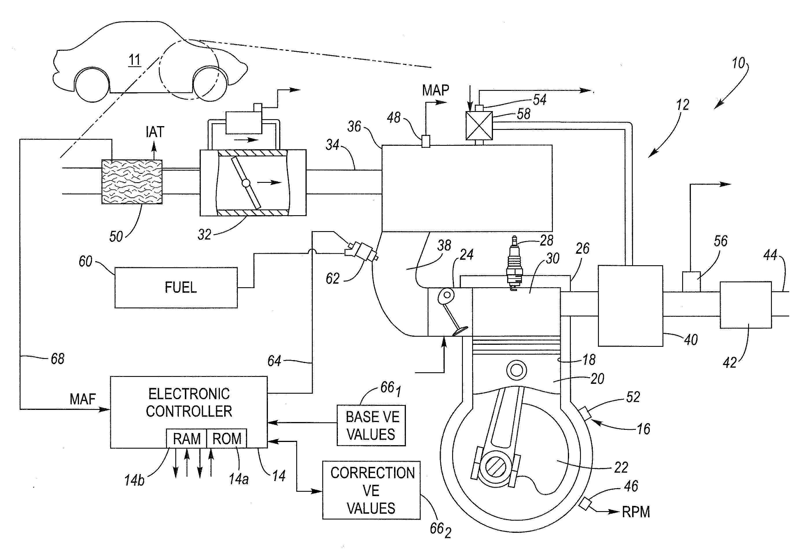
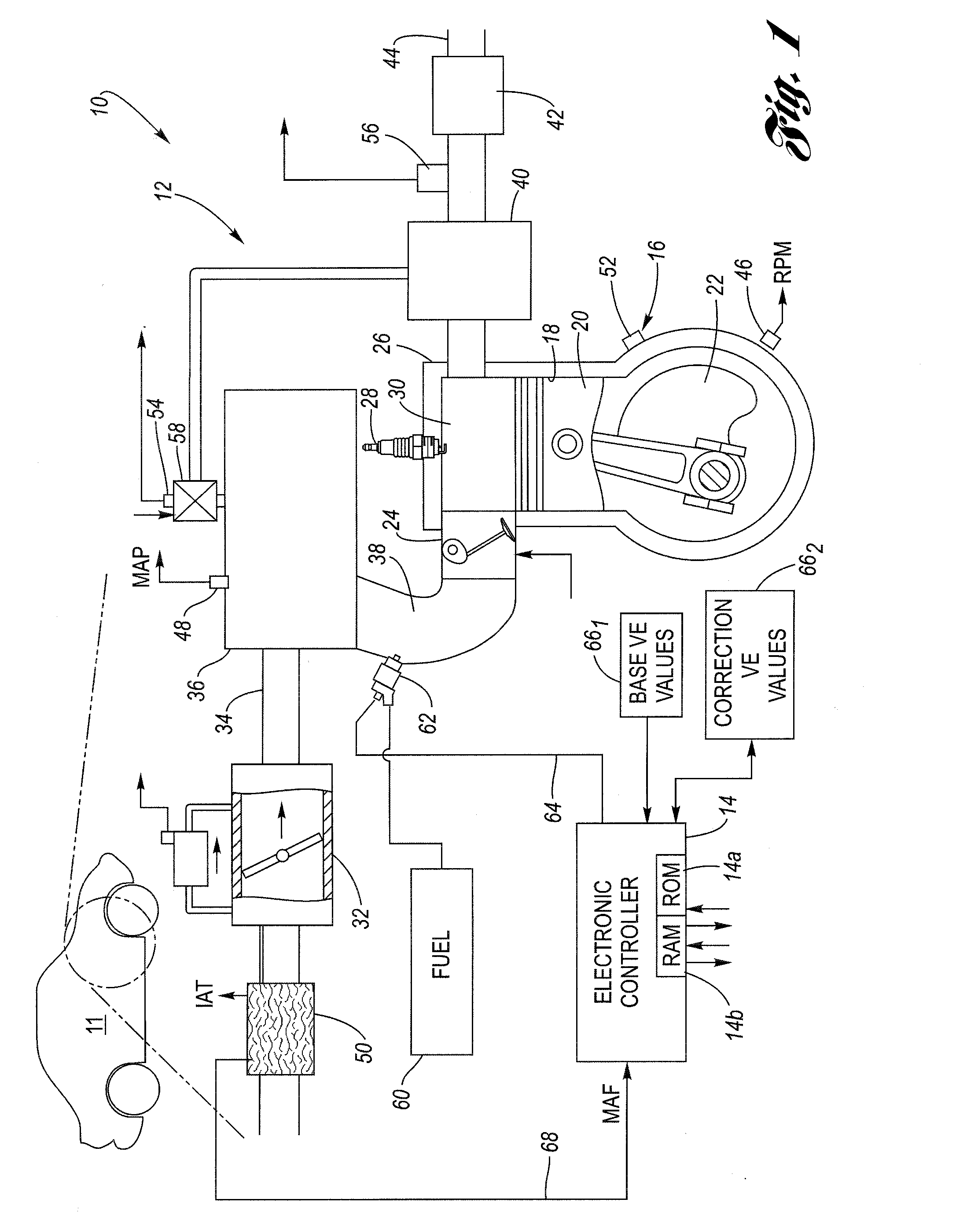
[0016]Referring now to the drawings, wherein the Figures are for the purpose of illustrating an embodiment of the invention only, FIG. 1 shows an internal combustion engine system 10 in an automotive vehicle 11. The system 10 includes an internal combustion engine 12 controlled by an electronic engine controller 14, all in accordance with the present invention. Engine 12 may be a spark-ignition engine that includes a number of base engine components, sensing devices, output systems and devices, and a control system.

[0017]Electronic controller 14 is configured via suitable programming to contain various software algorithms and calibrations, electrically connected and responsive to a plurality of engine and vehicle sensors, and operably connected to a plurality of output devices. Controller 14 includes at least one microprocessor, associated memory devices such as read only memory (ROM) 14a and random access memory (RAM) 14b, input devices for monitoring input from external analog and...


PUM

PropertyMeasurementUnit
mass air flowaaaaaaaaaa
speed-aaaaaaaaaa
massaaaaaaaaaa

Abstract

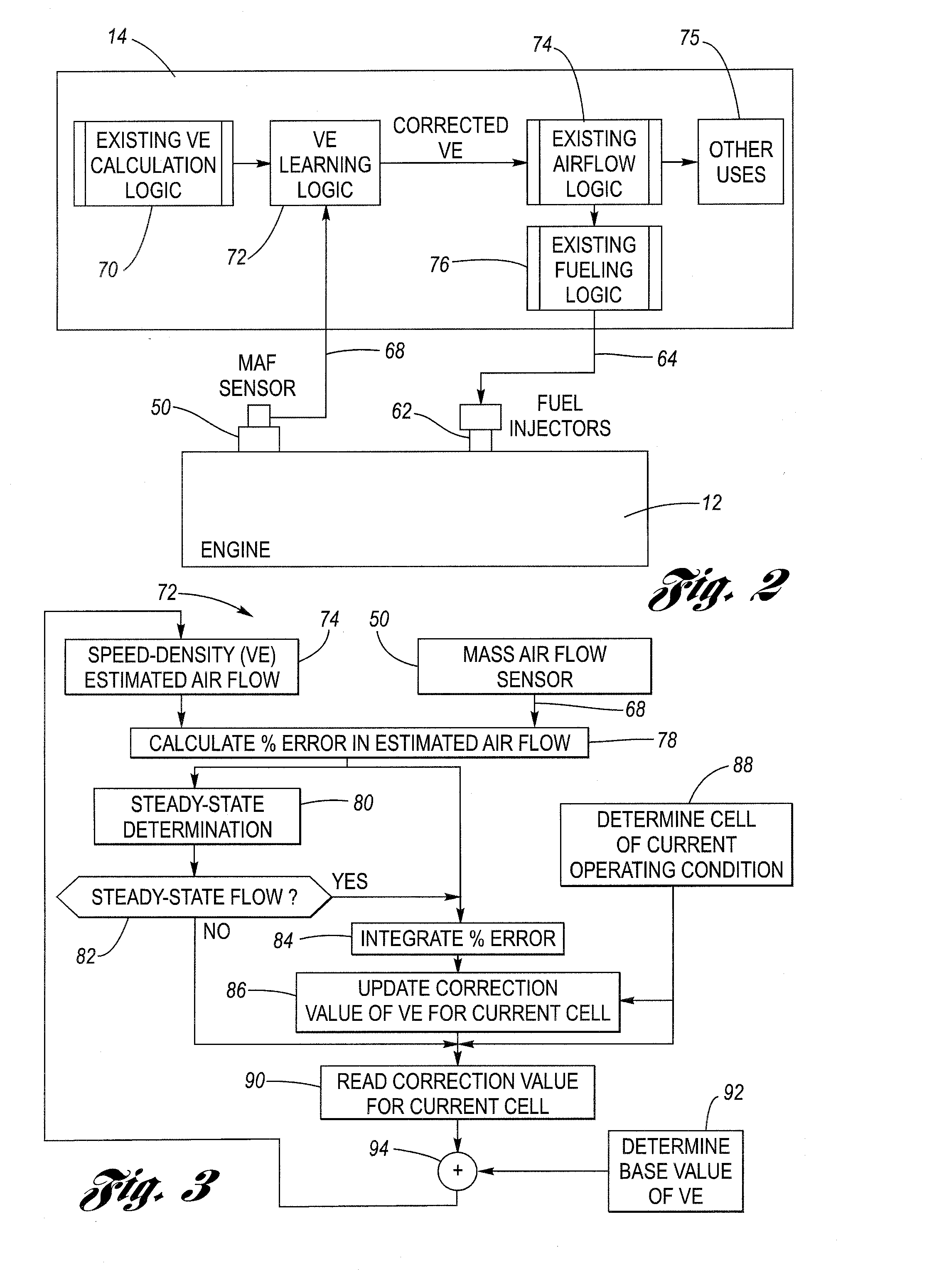
An electronic engine controller is configured to execute a process of adapting a base value of the volumetric efficiency of an engine through the addition of a correction value of the volumetric efficiency. The process includes comparing an estimated mass air flow value calculated using a speed-density equation, with an actual mass air flow value measured by a mass air flow (MAF) sensor. A percentage error of the estimated mass air flow value as compared to the actual mass air flow value is calculated. When the percentage error indicates that the air flow is at steady state, then the process updates the VE correction value, by integrating the percentage error. The new correction value, thus computed, is then stored in a cell of an array corresponding to the current engine operating condition. The process is configured to add the correction value to the corresponding base value to produce an updated value of the VE, valid for that operating condition. The process accommodates changes in the volumetric efficiency of the engine due to part aging and deposit build-up over time, among other things. The updated VE value may then be used for mass air flow estimation and accordingly for fueling control as well.

Description

TECHNICAL FIELD [0001]The present invention relates to a method for on-line adaptation of engine volumetric efficiency using a mass air flow sensor.BACKGROUND OF THE INVENTION [0002]Accurate control of engine air / fuel ratio requires knowledge of the mass air flow entering the engine cylinders in each combustion cycle. Ordinarily, this can be relatively accurately determined through a speed-density calculation based on the measured engine speed and intake manifold temperature and absolute pressure, taking into account various factors including the volumetric efficiency (VE) of the engine, as seen by reference to U.S. Pat. No. 6,393,903 entitled VOLUMETRIC EFFICIENCY COMPENSATION FOR DUAL INDEPENDENT CONTINUOUSLY VARIABLE CAM PHASING to Reed et al., assigned to the common assignee of the present invention, and incorporated herein by reference in its entirety. The volumetric efficiency of an engine in turn may be calibrated on a small number of prototype engines during development. Thi...

Claims


Application Information

Patent Timeline
Patent Type & Authority Applications(United States)
IPC IPC(8): G01L3/26G01M15/04
CPCF02D41/185G01M15/042F02D41/2451F02D41/187
Inventor OLIN, PETER M.QUELHAS, SERGIOYANG, KOON CHULGARCIA, SERGIO E.
Owner DELPHI TECH INC
Learn More