Damping motor and control approach for mitigating torsional backlash, damping critical geartrain speeds, and providing improved torque control in mechanical gears

a technology of damping motor and damping gear, which is applied in the direction of gearing, lifting equipment, transportation and packaging, etc., can solve the problems of gear teeth being transiently disengaged and reengaged, the speed at which the two devices operate is incompatible, so as to reduce torsional resonance, improve output torque control, and mitigate backlash problems

Active Publication Date: 2009-02-26
FLORIDA STATE UNIV RES FOUND INC
View PDF6 Cites 1 Cited by
  • Summary
  • Abstract
  • Description
  • Claims
  • Application Information

AI Technical Summary

Benefits of technology

[0016]The present invention comprises a torque damper motor connected to the output side of a mechanical gear system. The damper motor, along with its associated control system, mitigates backlash problems, reduced torsional resonance, and provides improved output torque control. In the preferred embodiment, the damper motor is powered by a power electronics-based variable speed drive. The damper motor can be significantly less powerful than the overall rating of the gear system (typically 5-10% of the overall rating) while still providing the enhanced performance.

Problems solved by technology

Unfortunately, the speeds at which the two devices operates are incompatible.
While the reduction gearbox solves the speed compatibility issue, it introduces other problems.
Those skilled in the art will know that every set of mating gears creates a backlash issue.
However, when the load varies (or the system is unloaded or reversed), the gear teeth may become transiently disengaged and reengaged.
This can produce resonant problems, as well as excessive gear tooth wear.
Gear systems employing these solutions are often expensive to manufacture.
However, the gears still experience additional stress under dynamic loading and unloading conditions.
Furthermore, tight gear interface tolerances often increase mechanical friction and present lubrication problems.
Backlash within a gear system also causes problems with resonance.
When operated around these critical speeds, cyclic torsional vibration tends to increase.
Vibration obviously reduces gear and bearing life.
However, in many large systems, it is simply unsafe to operate the gear train at a critical speed.
However, those skilled in the art will realize that such control is often impossible.

Method used


Image

  • Damping motor and control approach for mitigating torsional backlash, damping critical geartrain speeds, and providing improved torque control in mechanical gears
  • Damping motor and control approach for mitigating torsional backlash, damping critical geartrain speeds, and providing improved torque control in mechanical gears
  • Damping motor and control approach for mitigating torsional backlash, damping critical geartrain speeds, and providing improved torque control in mechanical gears

Examples


Embodiment Construction

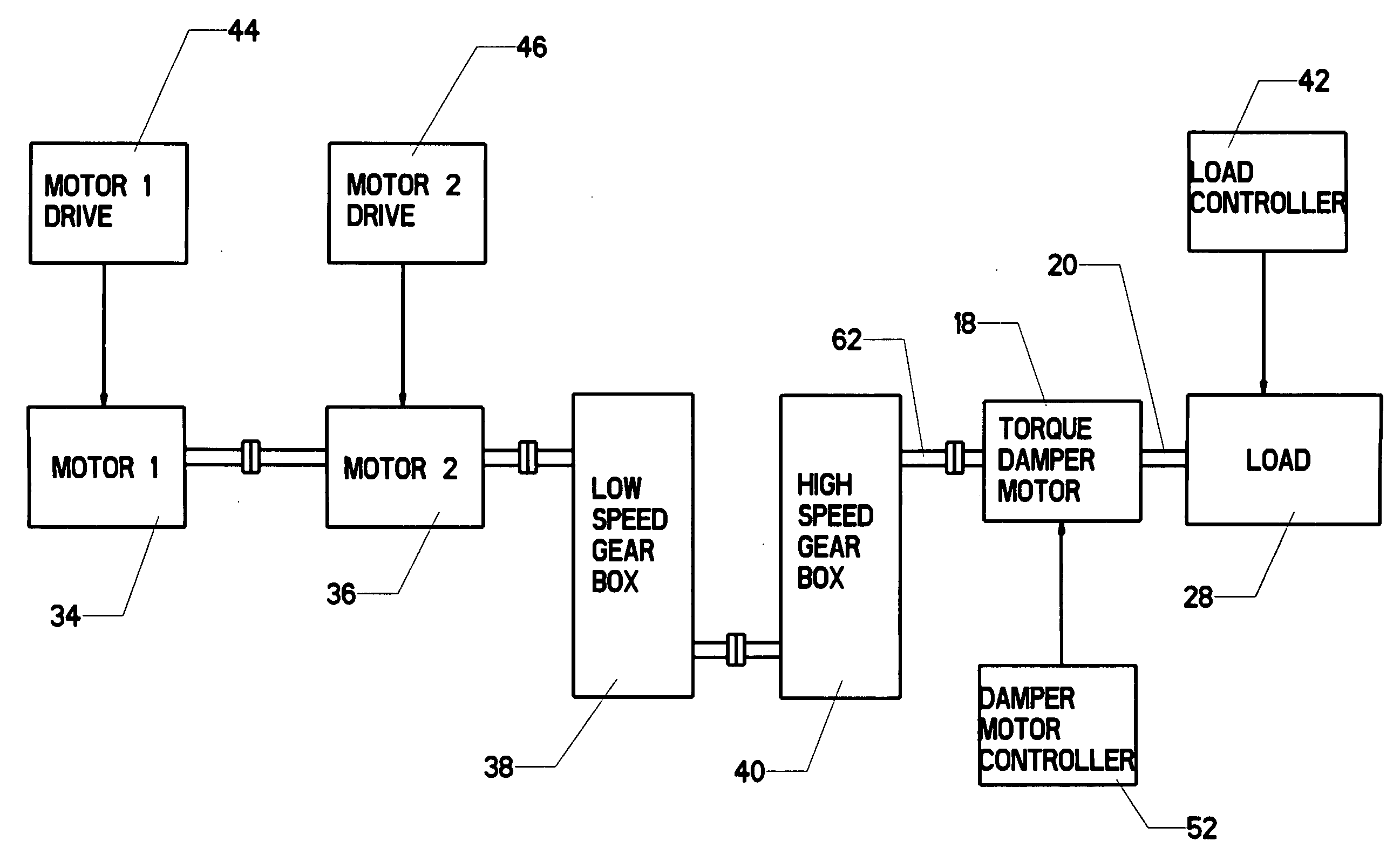
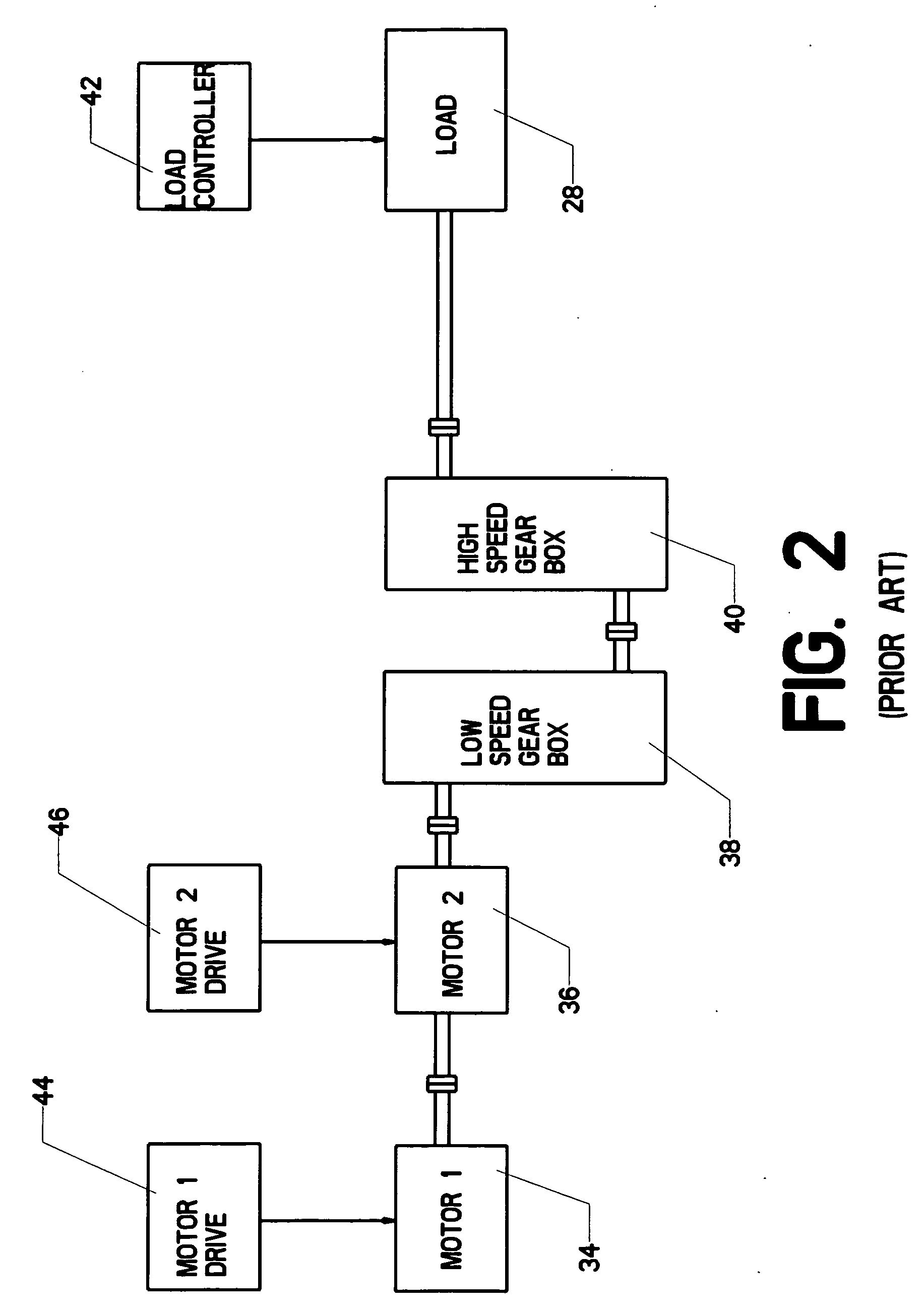
[0024]The present invention proposes adding a controlled torque damper motor on the output side of a rotating mechanical system. FIG. 3 shows the addition of such a motor to the system of FIG. 2. In FIG. 3, the reader will observe that torque damper motor 18 has been added between high speed gearbox 40 and load 28. Gearbox output shaft 62 provides the rotating output from the two gearboxes. It is directly connected to load shaft 20, which powers load 28. Torque damper motor 18 rotates in unison with load shaft 20. It could be directly connected to the gearbox output shaft, or attached to the load shaft itself.

[0025]Rapid control of the torque damper motor is preferable, so damper motor controller 52 is provided. This provides rapid fluctuation in both the magnitude and direction of the torque produced by the torque damper motor. Those skilled in the art will know that such control can be provided by a variety of known methods. However, one good approach is to use a pulsed output fro...


PUM


Abstract

A torque damper motor connected to the output side of a mechanical gear system. The damper motor, along with its associated control system, mitigates backlash problems, reduced torsional resonance, and provides improved output torque control. In the preferred embodiment, the damper motor is powered by a power electronics—based variable speed drive. The damper motor can be significantly less powerful than the overall rating of the gear system (typically 5-10% of the overall rating) while still providing the enhanced performance.

Description

STATEMENT REGARDING FEDERALLY SPONSORED RESEARCH OR DEVELOPMENT[0001]This invention was developed using United States Department of Defense funding issued through a grant by the Office of Naval Research (Grant No. N0014-02-1-0623).CROSS-REFERENCES TO RELATED APPLICATIONS[0002]This is a non-provisional application claiming the benefit-pursuant to 37 C.F.R. §1.53(c) of an earlier-filed provisional application. The provisional application was filed on Aug. 21, 2007 and was assigned application Ser. No. 60 / 965,680. The provisional application listed the same inventor.MICROFICHE APPENDIX[0003]Not ApplicableBACKGROUND OF THE INVENTION[0004]1. Field of the Invention[0005]This invention relates to the field of mechanical gear systems. More specifically, the invention comprises a controlled damper motor placed between the gearbox output and the load.[0006]2. Description of the Related Art[0007]Many mechanical systems require the use of speed-changing gears. These are conventionally housed in...

Claims


Application Information

Patent Timeline
Patent Type & Authority Applications(United States)
IPC IPC(8): F16H55/18
CPCF16F15/18Y10T74/19623Y10T74/19014F16H57/0006
Inventor STEURER, MICHAEL
Owner FLORIDA STATE UNIV RES FOUND INC
Why Eureka
Try Eureka