Serpentine structures for continuous flow particle separations

a technology sedimentation structure, which is applied in the direction of sedimentation settling tank, separation process, laboratory glassware, etc., can solve the problems of increasing the complexity of the device, particular field method, and the growth of most of the techniques, so as to improve the operation

Inactive Publication Date: 2009-02-26
PALO ALTO RES CENT INC
View PDF81 Cites 53 Cited by
  • Summary
  • Abstract
  • Description
  • Claims
  • Application Information

AI Technical Summary

Benefits of technology

[0016]In another aspect of the presently described embodiments, the serpentine channels may have converging or diverging cross-sections to take advantage of the pressure derivative: dp / dR∝1 / R2.
[0017]In another aspect of the presently described embodiments, the channel may use a vertical compression field to load particles against the bottom of the channel for improved operation.

Problems solved by technology

Most of these techniques have seen exponential growth but are batch processes that require set-up time for each sample lot.
Though the FFF technique is versatile and has the potential to be miniaturized, the requirement of an external field may increase the complexity of the device.
Also the use of a particular field method might limit its area of application to certain reagents (e.g. Magnetic FFF).
Moreover, many of these techniques are limited to batch processing and are scaled to handle only minute volumes of samples.
Further, many of these processes are typically designed for only a centrifugal mode of operation.

Method used


Image

  • Serpentine structures for continuous flow particle separations
  • Serpentine structures for continuous flow particle separations
  • Serpentine structures for continuous flow particle separations

Examples


Embodiment Construction

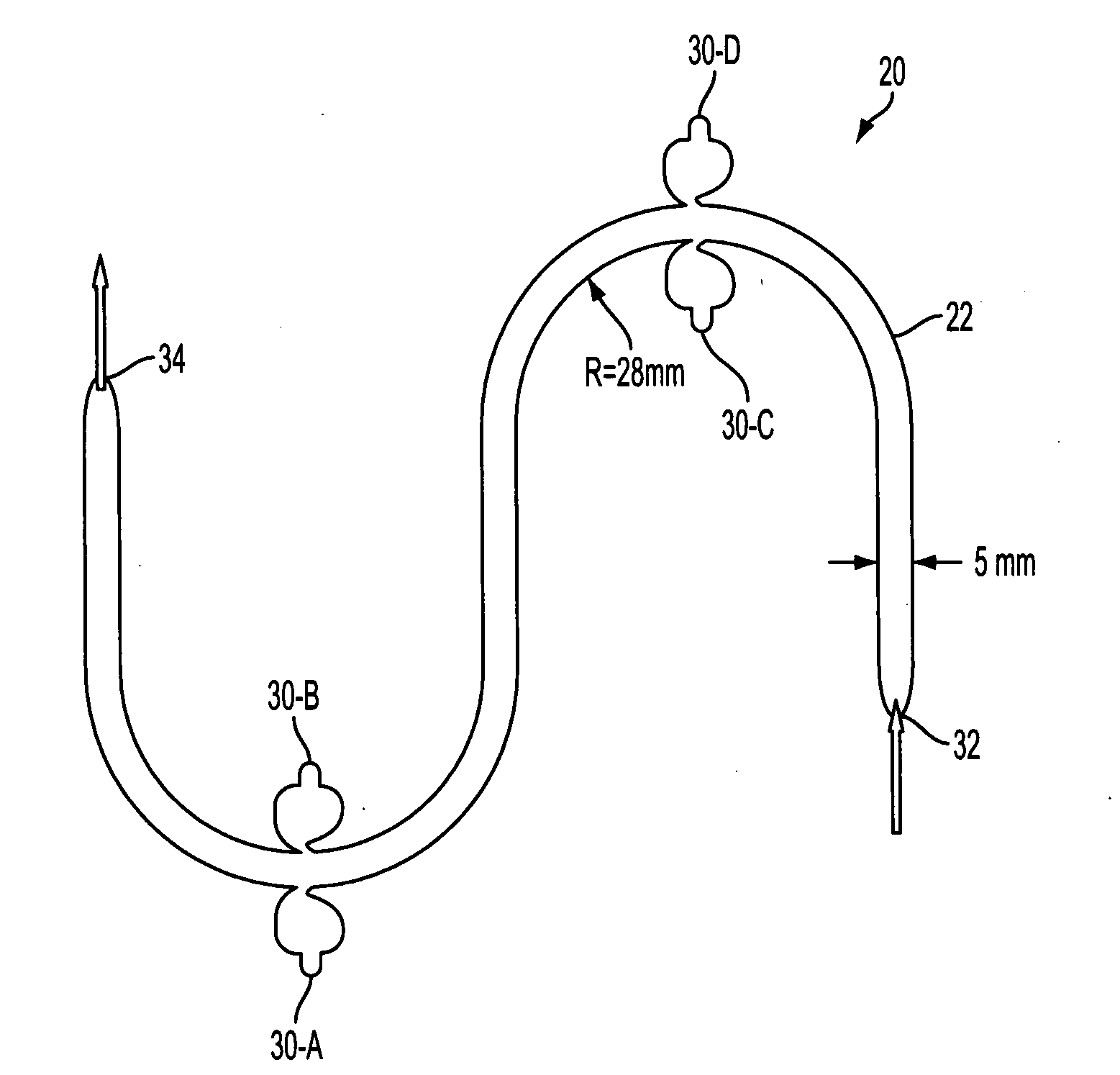
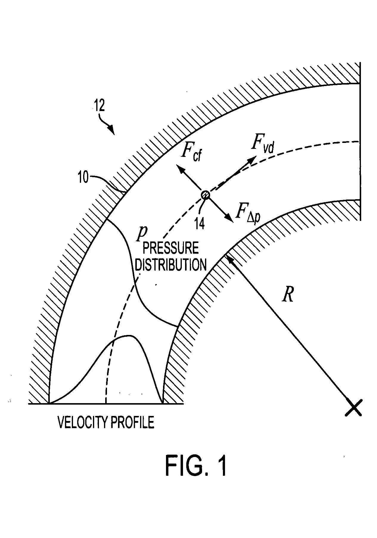
[0044]The presently described embodiments provide a system that allows for separation of particles within a fluid (such as biological matter) based on size and mass of the particles. This is accomplished in one form using a serpentine channel. In this case, the curved sections of the channel provide interplay between the outward directed centrifugal force and the inward directed transverse pressure field from fluid shear. In this regard, two modes of operation are implemented. At high fluid velocity, centrifugal force dominates and particles tend to move outward. At low fluid velocity, transverse pressure dominates and the particles tend to move inward in the channel. The magnitudes of the opposing forces depend on flow velocity, particle size, radius of curvature of the curved sections of the channel, channel dimensions and viscosity of the fluid.

[0045]Strategically positioned and shaped collection chambers de-couple the flow field but allow particles to enter for collection, and t...


PUM

PropertyMeasurementUnit
semicircular radiusaaaaaaaaaa
viscosityaaaaaaaaaa

Abstract

An improved technique for particle separation is provided. A serpentine structure is utilized in a continuous fluid flow environment to allow for suitable separation of particles to occur in a manner that does not require external application of forces to initiate the separation. The geometry of the serpentine structure and associated forces generated in connection with fluid flow therein suffice.

Description

GOVERNMENT FUNDING[0001]This project has been funded under Army Research Office (ARO) contract: W91 1 NF-05-C-0075.BACKGROUND[0002]Particle separation and sorting represents an important requirement especially in biological and chemical processes for both macro-scale and miniaturized lab-on-chip applications. Some of the methods employed today are mechanical sieving and sedimentation which are usually reserved for separation of large particles. Techniques such as hydrodynamic chromatography, size exclusion chromatography and electrophoresis allow separation of smaller particles. Most of these techniques have seen exponential growth but are batch processes that require set-up time for each sample lot.[0003]Field Flow Fractionation (FFF) is another macro-scale separation technique which is 30 years old but has attracted recent interest in microfluidics. This technique requires a transverse field which may be polarization, acoustic, magnetic, thermal, optical, or centrifugal, to sort a...

Claims


Application Information

Patent Timeline
Patent Type & Authority Applications(United States)
IPC IPC(8): B03B5/00
CPCB01L3/502761B01D2221/10B01D21/265B01D21/0087
Inventor LEAN, MENG H.KOLE, ASHUTOSHSEO, JEONGGI
Owner PALO ALTO RES CENT INC
Why Eureka
Try Eureka