Three dimensional image processing apparatus and x-ray diagnosis apparatus

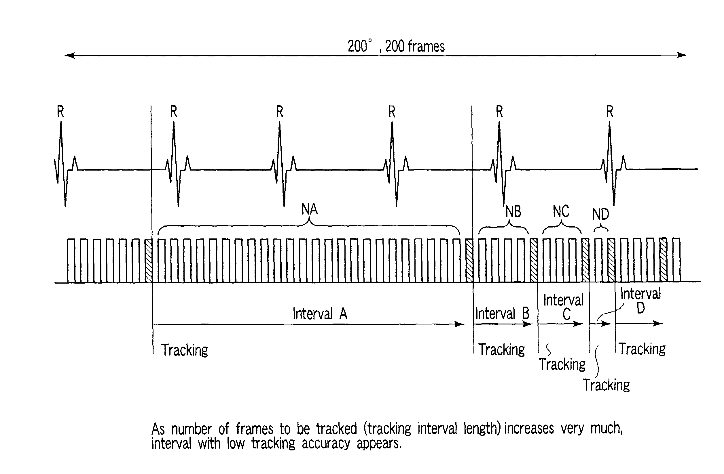
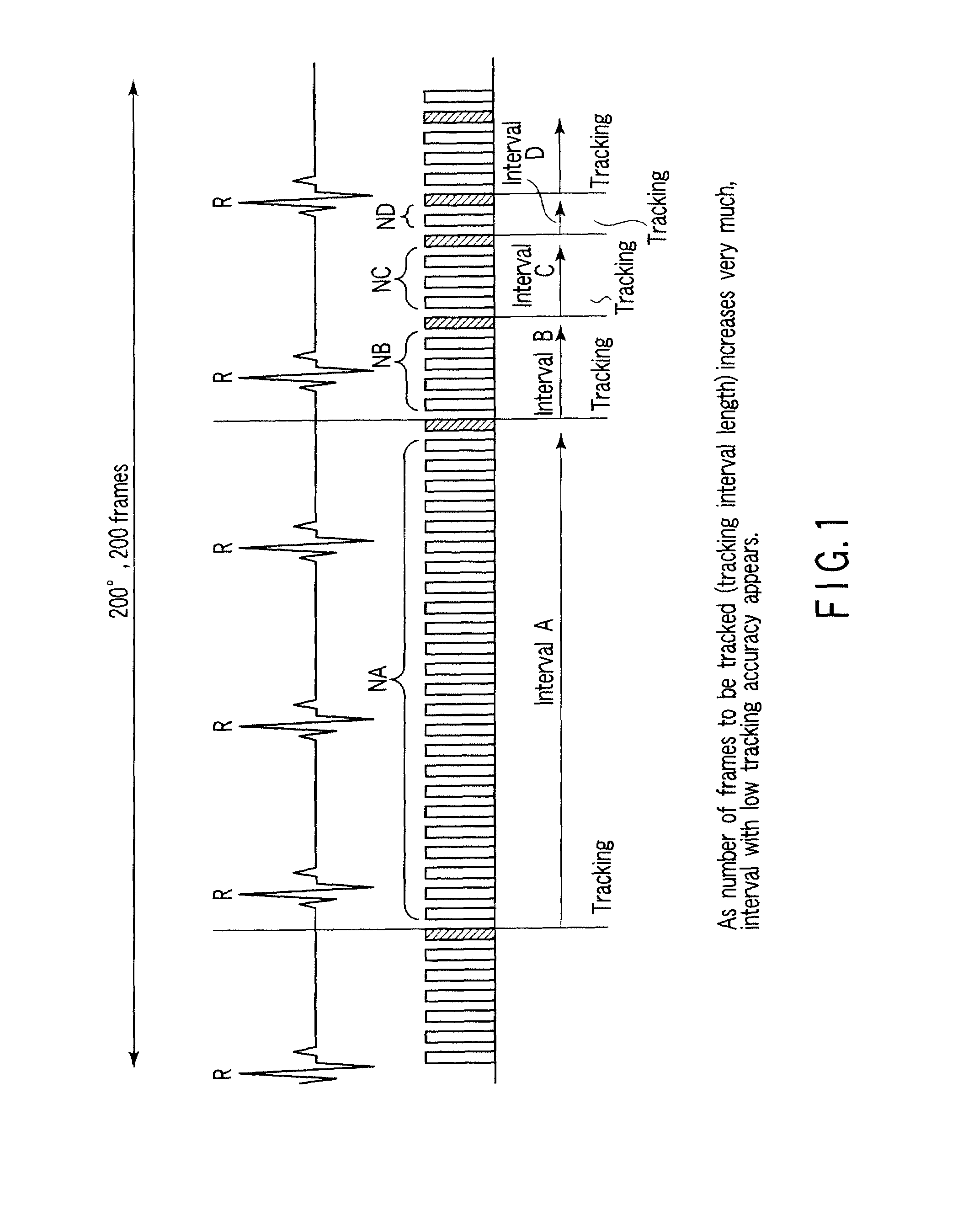
a three-dimensional image and image processing technology, applied in material analysis using wave/particle radiation, instruments, nuclear engineering, etc., can solve the problems of large motion blur, unsuitable diagnosis image quality, arbitrariness, etc., to suppress variations in tracking interval length and stabilize image quality. a reconstructed image

Active Publication Date: 2009-02-26
TOSHIBA MEDICAL SYST CORP
View PDF10 Cites 14 Cited by
  • Summary
  • Abstract
  • Description
  • Claims
  • Application Information

AI Technical Summary

Benefits of technology

[0009]It is an object of the present invention to stabilize the image quality

Problems solved by technology

Since the cardiovascular vessel moves, reconstructing its image by a conventional technique causes a large motion blur.
The image quality of the reconstructed image is unsuitable for diagnosis.
However, the operation which the operator performs to designate feature points accompanies arbitrariness.
This arbitrariness makes the image qualit

Method used


Image

  • Three dimensional image processing apparatus and x-ray diagnosis apparatus
  • Three dimensional image processing apparatus and x-ray diagnosis apparatus
  • Three dimensional image processing apparatus and x-ray diagnosis apparatus

Examples


first modification

(First Modification)

[0082]If arrhythmia has occurred as shown in FIG. 14, no images are automatically selected from the corresponding heartbeat. In a heartbeat with arrhythmia, since the movement of the heart is not steady, it is difficult for the operator to designate a feature point. In order to save the operator from performing difficult operation, therefore, the apparatus does not automatically select any images with arrhythmia. When determining the presence of arrhythmia, the apparatus monitors heart rates (RR intervals), and determines a heartbeat accompanying an abrupt decrease or increase in RR interval by using a threshold.

[0083]In addition, when arrhythmia occurred as shown in FIG. 15, it suffices to automatically select many images in the corresponding heartbeat. In a heartbeat with arrhythmia, since the movement of the heart is not steady, the tracking performance deteriorates. Therefore, prompting the operator to input feature points in many images will stabilize the tr...

second modification

(Second Modification)

[0084]Key images are stably and automatically selected by the first to fifth techniques described above. Each technique further includes a function of allowing the operator to change an automatically selected key image at his / her own discretion. Assume that image #34 is automatically selected as a key image by one of the first to fifth techniques. The key image of image #34 is displayed on the screen to prompt the operator to select a feature point. When, however, the operator operates the “→” mark displayed on an end of the screen or the “→” key on the keyboard at his / her own discretion, image #35 adjacent to the automatically selected key image is set as a new key image. The operator can designate a feature point on image #35.

[0085]If, for example, a feature point overlaps a blood vessel on an automatically selected key image, it is difficult for the operator to identify the feature point. In such a case, it is possible to change (replace) the automatically se...

third modification

(Third Modification)

[0092]When no R wave can be detected in an electrocardiogram of a subject to be examined or R-R intervals extremely vary, the key image selection unit 7 discards an initially automatically selected key image, and forcibly selects key images at equal time intervals regardless of cardiac phases. Alternately, the key image selection unit 7 discards an initially automatically selected key image and prompts the operator to manually designate a key image.


PUM


Abstract

A three dimensional image processing apparatus includes a storage unit storing data of images in different radiographing directions together with information concerning cardiac phases, a key image selection unit selecting key images from the images, a feature point designation unit designatting feature points on the selected key images in accordance with operation by an operator, and an image reconstruction unit reconstructing a three dimensional image from the images on the basis of positions of the designated feature points, wherein the key image selection unit selects, as the key images, a pair of images which are located at the same cardiac phase and whose radiographing directions are different by a substantially predetermined angle and images spaced apart from each other by an angle obtained by substantially equally dividing an interval between the pair of images by a predetermined number.

Description

BACKGROUND OF THE INVENTION[0001]1. Field of the Invention[0002]The present invention relates to a three dimensional image processing apparatus which reconstructs a three dimensional image from a plurality of X-ray images obtained in different radiographing directions.[0003]2. Description of the Related Art[0004]Three dimensional image reconstruction processing is to be performed for a moving object, more specifically, for example, a cardiovascular vessel. Since the cardiovascular vessel moves, reconstructing its image by a conventional technique causes a large motion blur. The image quality of the reconstructed image is unsuitable for diagnosis. There have been proposed several countermeasure techniques for such a problem. For example, the position of a region on an image is corrected, and a three dimensional image is reconstructed from the corrected image.[0005]This technique generates, for example, 200 images at different radiography angles. The operator selects several discrete ...

Claims


Application Information

Patent Timeline
IPC IPC(8): G01N23/00
CPCG01N2223/419G01N23/046
Inventor SAKAGUCHI, TAKUYASILVER, MICHAEL D.YAO, JINGWUCHEN, MEIBOZHILOV, STEFANOHISHI, SATORU
Owner TOSHIBA MEDICAL SYST CORP
Why Eureka
Try Eureka