Sampling Device for Viscous Sample, Homogenization Method for Sputum and Method of Detecting Microbe

a technology of viscous sample and sampling device, which is applied in the field of viscous sample sampling device, homogenization method of sputum and detection method, can solve the problems of deteriorating quantitativeness of liquid sample having a relatively high viscosity such as sputum, and the inability to discharge the entire amount of aspirated viscous sample, etc., to achieve low aspiration and discharge power, improve quantitativeness, and reduce the burden on the operator

Inactive Publication Date: 2009-02-26
EISIA R&D MANAGEMENT CO LTD
View PDF97 Cites 21 Cited by
  • Summary
  • Abstract
  • Description
  • Claims
  • Application Information

AI Technical Summary

Benefits of technology

[0040]According to the present invention, significant effects can be obtained in that there can be provided a sampling device for a viscous sample and an auxiliary jig therefor that can improve quantitativeness when sampling a viscous sample such as sputum, reduce a burden to an operator with a relatively low aspiration and discharge powers, improve clear-cutting property upon aspiration and discharge of the visco

Problems solved by technology

However, such devices have had a problem that while a liquid sample having a relatively low viscosity can be sampled more or less quantitatively, a liquid sample having a relatively high viscosity such as sputum (hereinafter, referred to as a “viscous sample”) is sampled with considerably deteriorated quantitativeness.
That is, with a conventional dropper or a pipette, which aspirates or discharges a viscous sample via air pressure, an entire amount of the aspirated viscous sample can not be discharged since a part of the viscous sample gets stuck on an inner wall of the dropper or pipette particularly when the viscous sample is discharged therethrough.
In addition, in the case of the conventional syringe 110, a relatively large aspiration power and discharge power are required, so a heavy burden rests on the operator.
As other factors, mention may be made of problems that with the conventional syringe 110, the viscous sample sticks and does not separate in a clear cut manner upon aspiration and discharge, so it is difficult to collect a necessary amount of the viscous sample and that the sticky viscous sample form strings, which attach to other sites, thus causing an issue of environmental public health.
However, the sputum of a patient generally has a high viscosity and it is difficult to have the sputum specimen uniformly smeared on a medium, resulting in an error in tests results.
Also, in gene tests, it is difficult to determine an exact number of microbes in the sputum as they

Method used


Image

  • Sampling Device for Viscous Sample, Homogenization Method for Sputum and Method of Detecting Microbe
  • Sampling Device for Viscous Sample, Homogenization Method for Sputum and Method of Detecting Microbe
  • Sampling Device for Viscous Sample, Homogenization Method for Sputum and Method of Detecting Microbe

Examples


example 1

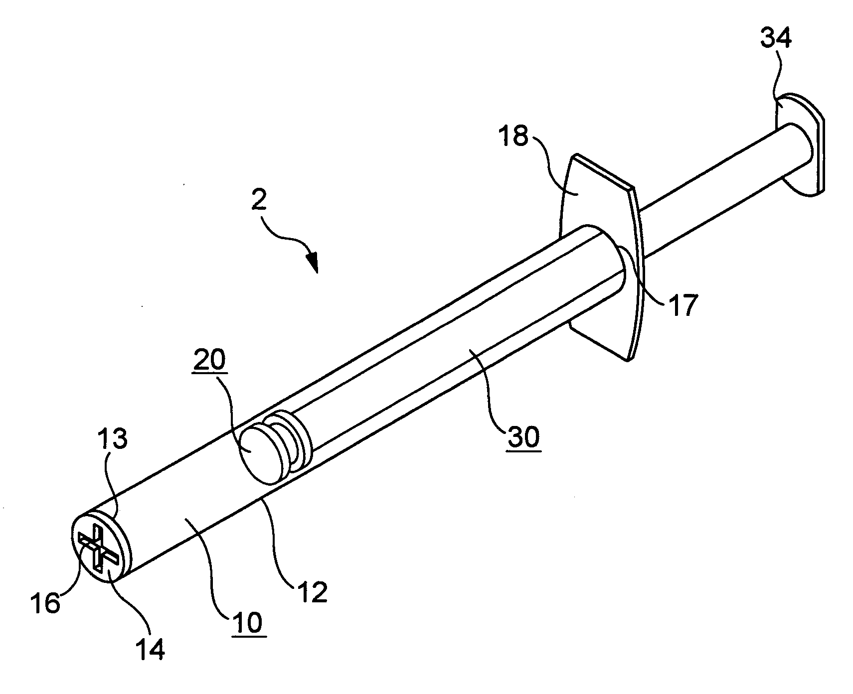
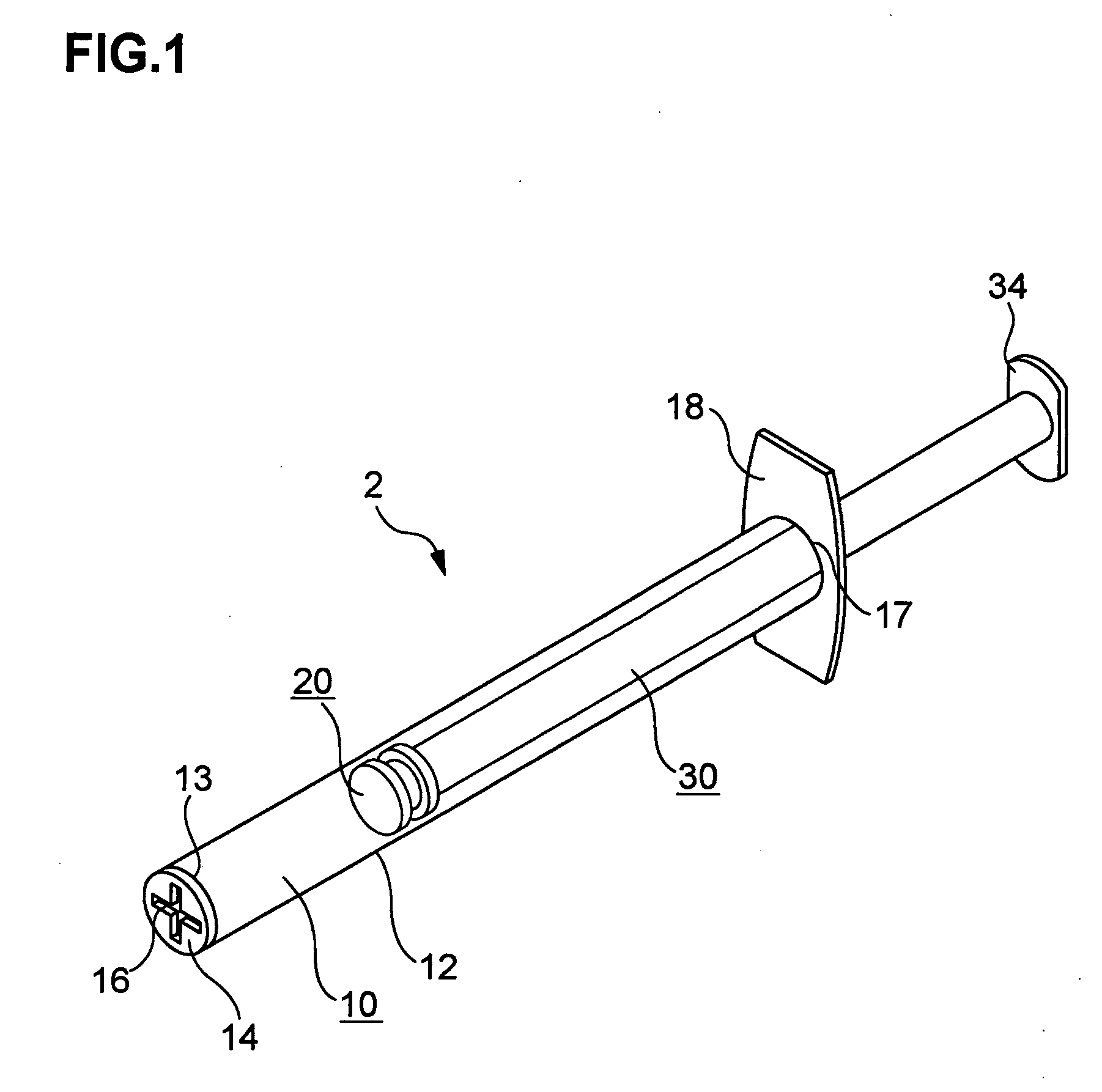
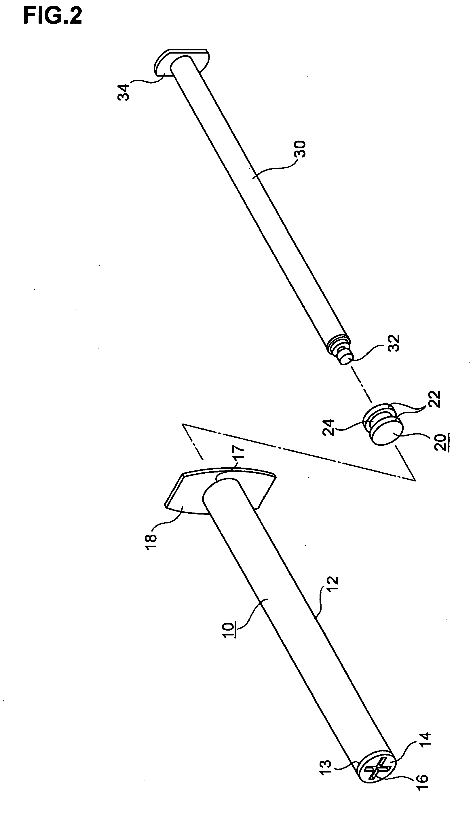
[0136]As a viscous sample resembling sputum, 8 g of pig stomach-derived mucin (manufactured by Wako Pure Chemical Industries, Ltd.) was sufficiently dissolved in 10 ml of 0.9% of sodium chloride solution to prepare 80% of mucin solution, which was used in the following procedure. As the sampling device 2 of the present invention, plate-like nozzles 14a to 14j having various types of slits (aspiration and discharge ports) 16a to 16j as shown in FIG. 3(a) to (j) were used for examining aspiration power and discharge power, respectively. The width of each slit was set to 1 mm and the volume was set to 1 ml. The testing apparatus as shown in FIG. 5 was used. FIG. 5 is a schematic explanatory diagram showing the apparatus used in measuring aspiration power and discharge power according to the present invention. FIG. 5(a) indicates the case of aspiration power and FIG. 5(b) indicates the case of discharge power. In FIGS. 5(a) and (b), symbol P represents a viscous sample, numeral 90 repre...

example 2

[0139]Using purulent sputum (P2, according to the classification of Miller & Jones) as the viscous sample and with the sampling device 2 of the present invention equipped with plate-like nozzles 14a to 14j having slits (aspiration and discharge port) of various shapes 16a to 16j as shown in FIG. 3(a) to (j), viscosity length (length of strings of a viscous sample) after aspiration and after discharge were examined. The width of each slit was set to 1 mm and the volume was set to 1 ml. The viscosity length after aspiration is determined as follows: after a predetermined amount of a viscous sample was aspirated from the container containing the viscous sample using the sampling device 2 of the present invention, the distal end of the sampling device 2 was once brought in contact with the bottom of the container and then drawn until a string of the viscous sample formed was broken. A distance from the bottom of the container to the height of the distal end of the sampling device 2 at w...

example 3

[0142]Using purulent sputum (P2, according to the classification of Miller & Jones) as the viscous sample and with the sampling device 2 of the present invention equipped with plate-like nozzles 14a to 14j having slits (aspiration and discharge port) of various shapes 16a to 16j as shown in FIG. 3(a) to (j), 500 μl each of the viscous sample was collected (aspirated and discharged in a separate container) and weight of the samples was measured. This procedure was repeated twice to determine quantitativeness of the test. The results obtained are shown in Table 3.


PUM


Abstract

It is intended to provide: a sampling device for quantitatively sampling a liquid sample having a high viscosity such as sputum; an auxiliary jig therefor; an agent for homogenizing sputum by which sputum can be quickly treated under mild conditions and a microbe contained in the sputum can be detected at an improved stability; a homogenization device; a homogenization method; a method of detecting a microbe by using the above method; a separation device for conveniently, quickly and efficiently collecting a microbe contained in sputum; a method of collecting a microbe; and a method of detecting a microbe by using the above method. A sampling device for a viscous sample includes: a tubular body; a gasket; a long rod-like plunger; a plate-shaped nozzle that has substantially the same diameter as that of a straight section of the tubular body and is adapted to close a distal end of the tubular body; and a slit formed in the plate-like nozzle, the slit having a predetermined shape adapted to serve as an aspiration and discharge port for aspirating and discharging the viscous sample.

Description

TECHNICAL FIELD[0001]The present invention relates to: a sampling device for quantitatively sampling a liquid sample having a high viscosity such as sputum; an auxiliary jig therefor; an agent for homogenizing sputum by which sputum can be quickly treated under mild conditions and microbe contained in the sputum can be detected at an improved stability; a homogenization device; a homogenization method; a method of detecting a microbe by using the above method; a separation device for conveniently, quickly and efficiently collecting a microbe contained in sputum; a method of collecting a microbe; and a method of detecting a microbe by using the above method.BACKGROUND ART[0002]It has heretofore been a common practice to use a dropper, a pipette or a syringe as a sampling device when a liquid sample which is a subject of a cultivation test (identification of microbes) or the like is collected and sampled. However, such devices have had a problem that while a liquid sample having a rel...

Claims


Application Information

Patent Timeline
IPC IPC(8): A61B5/00
CPCC12Q1/24G01N2015/0088G01N1/38
Inventor MORISHITA, TAKEHARUUSUI, MITSUGU
Owner EISIA R&D MANAGEMENT CO LTD
Why Eureka
Try Eureka