Method for estimating tire slip angle and a tire with sensors mounted therein

a technology of tire slip angle and sensor, which is applied in the direction of instruments, braking systems, transportation and packaging, etc., can solve the problems of affecting detection performance, yaw rate, and complicated corrections, and achieve the effect of improving the accuracy of estimating the slip angl

Inactive Publication Date: 2009-02-26
BRIDGESTONE CORP
View PDF3 Cites 39 Cited by
  • Summary
  • Abstract
  • Description
  • Claims
  • Application Information

AI Technical Summary

Problems solved by technology

However, the above method of estimating the slip angle from the steering angle, vehicle speed, yaw rate and lateral speed is heavily affected by external disturbances such as sensor errors and change of u of a road surface, and such a situation gives rise to a problem of demanding a complicated corrections in order to improve the estimation accuracy of the slip angle.
And further, the method of obtaining the slip angle by means of calculation based on a direct observation of t...

Method used


Image

  • Method for estimating tire slip angle and a tire with sensors mounted therein
  • Method for estimating tire slip angle and a tire with sensors mounted therein
  • Method for estimating tire slip angle and a tire with sensors mounted therein

Examples


embodiment 1

Preferred Embodiment 1

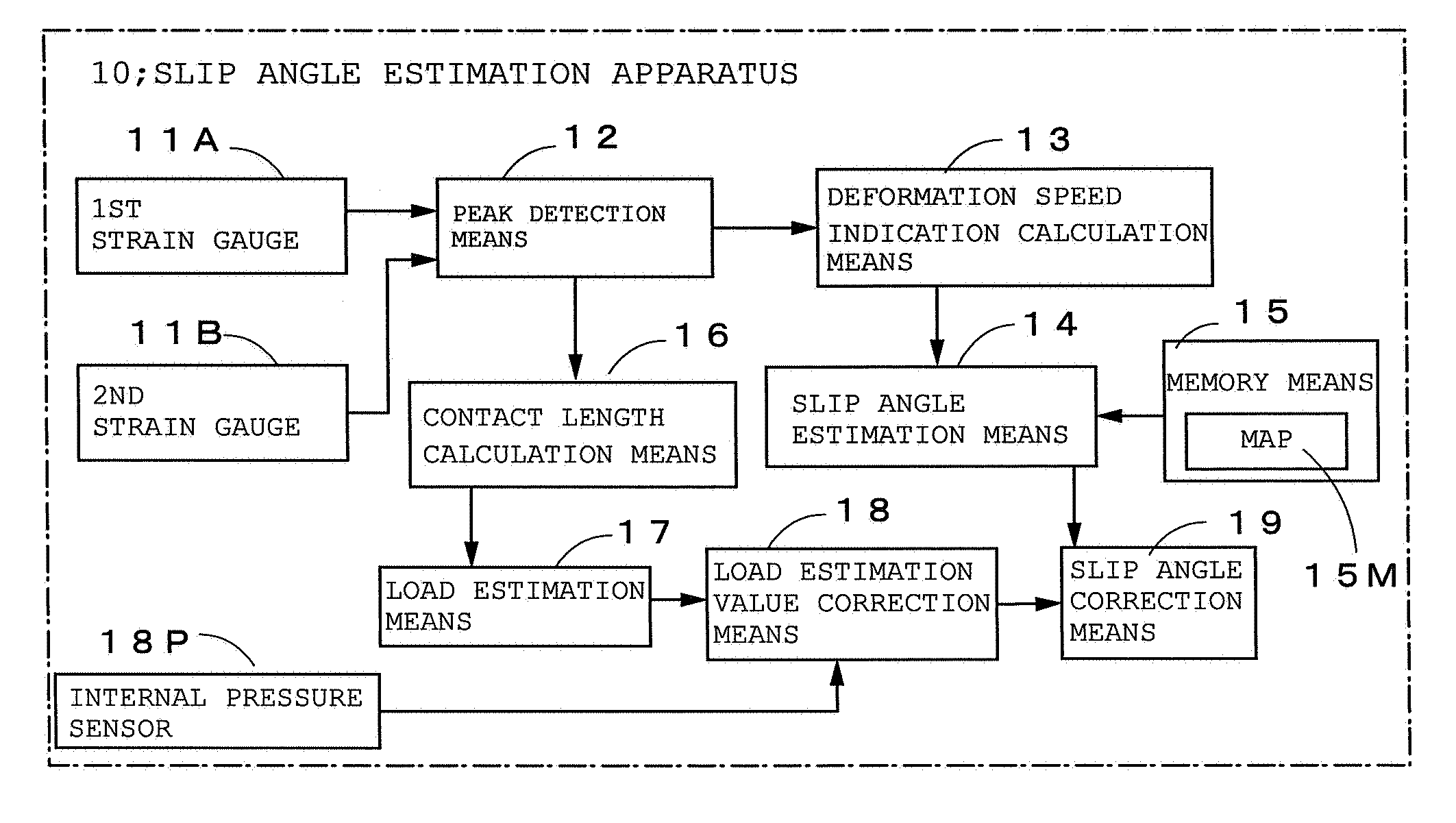
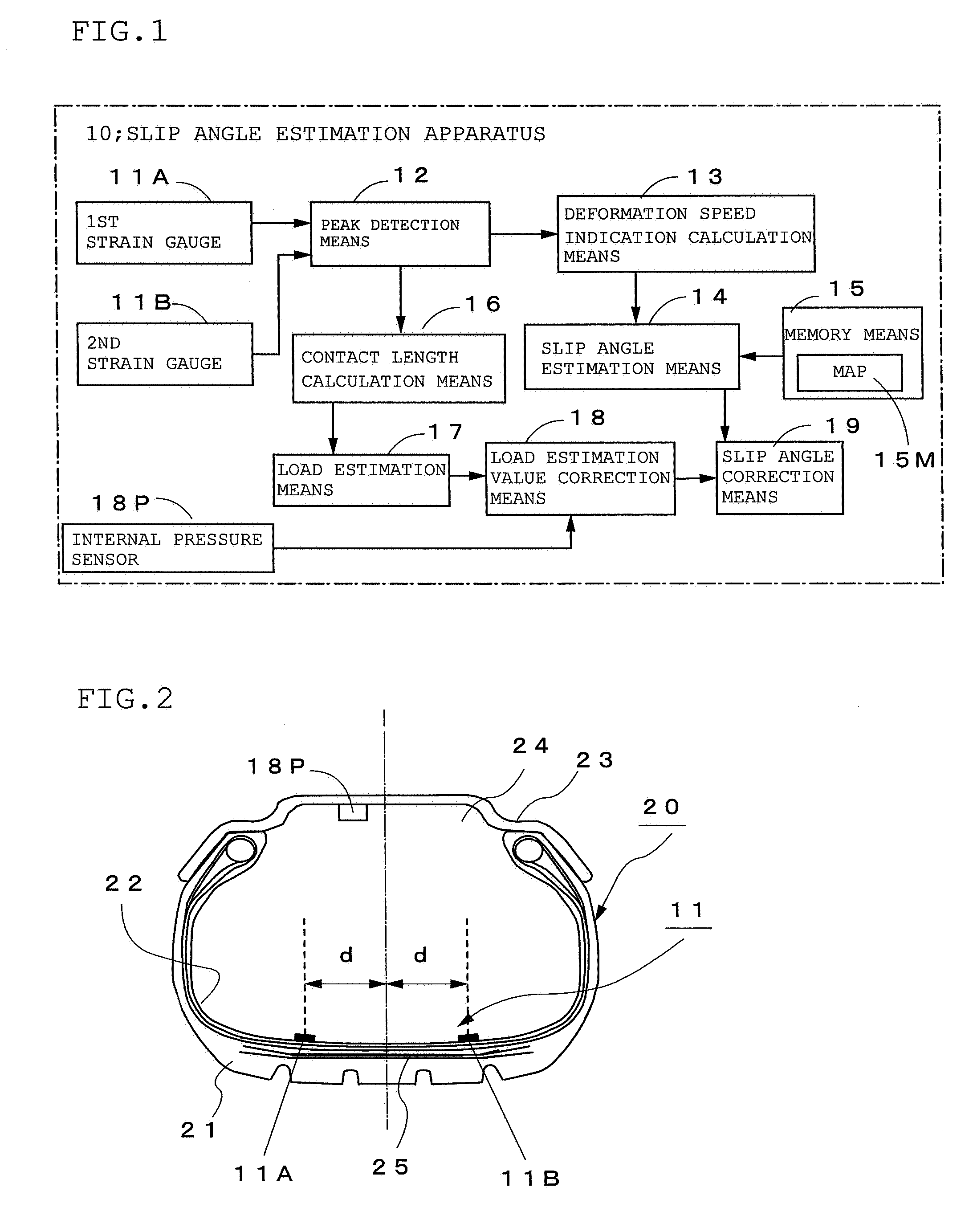
[0034]FIG. 1 is a block diagram showing constitution of the slip angle estimation apparatus 10, and FIG. 2 is a schematic diagram of the tire 20 with sensors mounted therein. In each of those drawings, reference numerals 11A and 11B denote the 1st and the 2nd strain gauges, respectively, for measuring deformation amount of the inner liner portion 22 deformed by the input from road surface to the tire tread 21 and those strain gauges 11A and 11B are mounted on the liner portion 22 of the tire 20 on the vehicle body side and the outer side, respectively at the positions located equally spaced apart in a tire axial direction and symmetrically with respect to the center thereof. The first and second strain gauges 11A and 11B constitute the paired sensors 11 according to the present invention.

[0035]The reference numeral 12 denotes a peak detection means for obtaining the deformation speed waveform by differentiating the deformation waveform detected by the paired se...

example 1

[0043]The tire with size of 225 / 55R17 having the configuration as shown by FIG. 2 is put on an indoor test equipment for running on a belt shaped flat road, and the deformation speed of the tire tread was detected from the output of a single paired strain gauges mounted to the tire which the slip angle was changed in constant levels up to ±8° under a constant load. In the above measurement, the internal pressure of the tire was kept at 230 Pa and running speed was kept constant at 60 km / h and loading was changed in seven levels between 200 N˜1000 N.

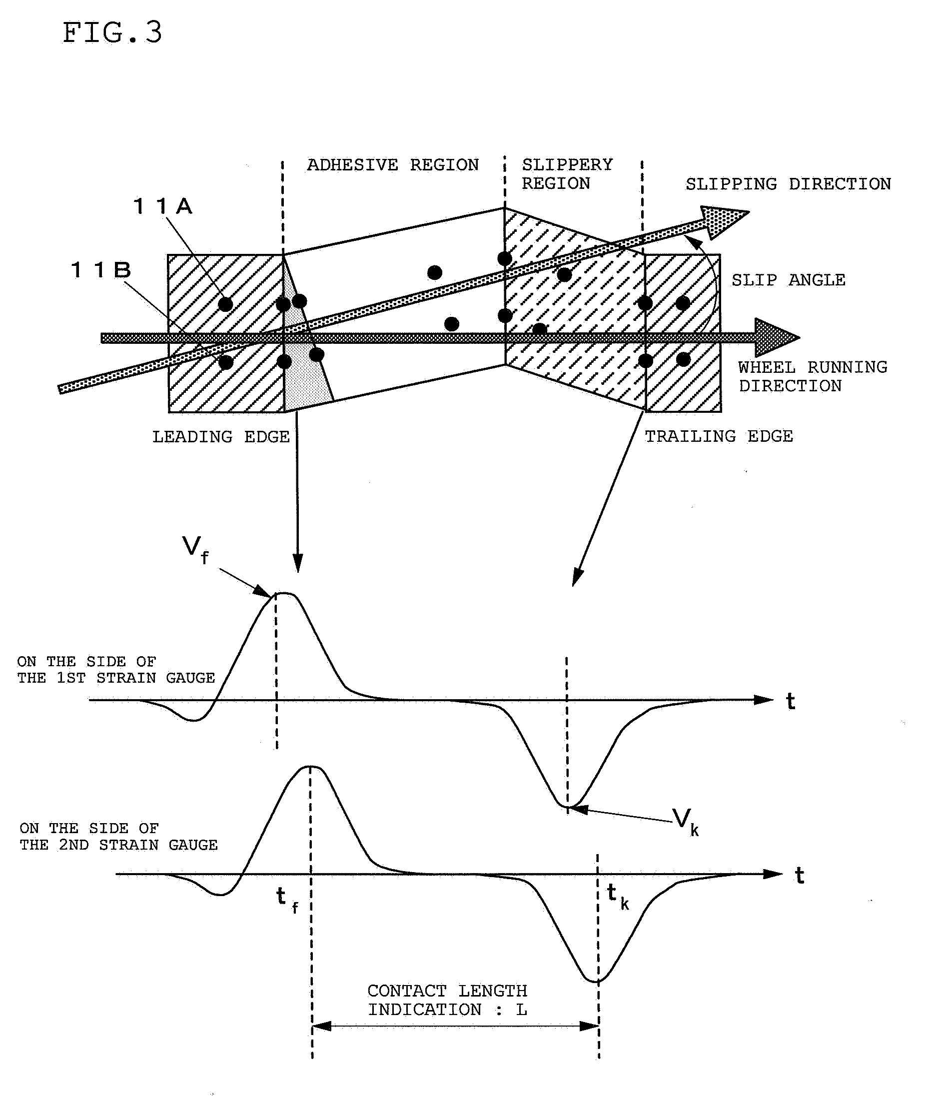
The graph as shown by FIG. 6 is a deformation speed waveform with the slip angle of +8° added measured at the inner liner portion. The peak in the positive direction of the waveform corresponds to the deformation speed Vf at the time of entering into the leading edge and, in this connection, the output from the strain gauge 1 on the side of the slip angle input becomes large and the one on the opposite side becomes small. In contrast with...

embodiment 2

[0044]In the preferred Embodiment 1, based on the deformation speed waveform obtained from the deformation waveform measured by the paired sensors 11 the peak values of the deformation speeds Vf1 and Vf2 from respective sensors 11 occurring at the time of entering into the leading edge when the tire tread entering into the contact portion with the road surface are detected and upon assigning those peak values as respective deformation speed indications, the slip angle is estimated from the ratio of the foregoing deformation speed indications, i.e., R=(Vf1 / Vf2) . However, plural paired sensors can be employed so as to obtain respective deformation speed indications from the peak values of deformation speed detected through at least two paired sensors. Then, upon obtaining the bending speed of the tire as a whole (total bending speed of the tire) based on the indication of the deformation speed from each pair of sensors, estimation of the tire slip angle can be made based on the total...


PUM


Abstract

Deformation of a tire is measured by a paired sensor 11 consisting of a 1st and 2nd strain gauges positioned on an inner liner of a tire with sensors mounted therein located equally spaced from and symmetrically with the center in an axial direction. Peak values of deformation speeds at the time of entering into the leading edge occurring at the time when the tire tread enters into the contact portion with a road surface are detected from the deformation wave from by differentiating with respect to time the wave form detected by the paired sensor and thus obtained peak values are designated as indication of deformation speed. Then, based on the ratio of thus obtained deformation wave indication and the Map 15M containing relation between thus obtained deformation speed ratio and time slip angle obtained beforehand, the slip angle of a vehicle under running condition is estimated, thereby enabling estimation of tire slip angle under vehicle running accurately.

Description

BACKGROUND OF THE INVENTION[0001]1. Field of the Invention[0002]The present invention is related to a method for estimating a tire slip angle of a vehicle under running condition and a tire with sensors for estimating the slip angle mounted therein.[0003]2. Description of the Related Art[0004]In order to improve the running stability of a vehicle, it has been sought to feed back a condition of tire such as tire slip angle to a vehicle control apparatus upon accurately estimating those conditions. By making use of that information, highly developed control by means of vehicle control apparatus can be available and thus further improvement in safety can be expected. As a method for estimating the above tire slip angle, several methods have been proposed such as estimation thereof from steering angle, vehicle speed, yaw rate and lateral acceleration, from utilizing Doppler effect of ultrasonic wave, from non-contact optical speed meter or from position information through GPS (for exam...

Claims


Application Information

Patent Timeline
IPC IPC(8): B60W40/10B60C23/00
CPCB60C23/0408B60T8/1725Y10T152/10B60T2240/04B60W2520/26B60T2230/02
Inventor NAGAYA, GO
Owner BRIDGESTONE CORP
Why Eureka
Try Eureka