System And Method For Controlling A Current Limit With Primary Side Sensing Using A Hybrid PWM and PFM Control

a technology of current limit control and hybrid side sensing, which is applied in the direction of power conversion systems, dc-dc conversion, instruments, etc., can solve the problems of degrading the control accuracy of cc current limit, affecting the control accuracy of constant current (cc) limit, and unable to directly use output current limit control techniques used in conventional systems. achieve the effect of accurate constant current control, minimize leakage inductance, and avoid acoustic nois

Active Publication Date: 2009-03-05
DIALOG SEMICONDUCTOR INC
View PDF6 Cites 66 Cited by
  • Summary
  • Abstract
  • Description
  • Claims
  • Application Information

AI Technical Summary

Benefits of technology

[0007]The present invention avoids very short (narrow) Ton times which ensures accurate constant current (CC) control with bipolar junction transistor (BJT) devices. The present invention also avoids acoustic noise because the switching frequency is maintained at a high enough level to avoid such acoustic noise even when the energy tr

Problems solved by technology

However, the output current limit control techniques used in conventional systems can not be directly used when a bipolar junction transistor (BJT) switching device is used instead of a MOSFET switching device, and when the pulse width modulation (PWM) switching frequency is relatively high, such as 65 kilohertz (kHz) and above.
As a consequence, when the output voltage is low, the Ton time can become very small.
However, when a BJT is used, the very-narrow Ton time can cause control problems and degrade the control accuracy of the CC current limit, because the BJT's normally have much longer turn-on and turn-off times which can be dynamically changed with line voltage and load.
This minimum Ton time

Method used


Image

  • System And Method For Controlling A Current Limit With Primary Side Sensing Using A Hybrid PWM and PFM Control
  • System And Method For Controlling A Current Limit With Primary Side Sensing Using A Hybrid PWM and PFM Control
  • System And Method For Controlling A Current Limit With Primary Side Sensing Using A Hybrid PWM and PFM Control

Examples


Embodiment Construction

[0012]A preferred embodiment of the present invention is now described with reference to the figures where like reference numbers indicate identical or functionally similar elements. Also in the figures, the left most digits of each reference number corresponds to the figure in which the reference number is first used.

[0013]Reference in the specification to “one embodiment” or to “an embodiment” means that a particular feature, structure, or characteristic described in connection with the embodiments is included in at least one embodiment of the invention. The appearances of the phrase “in one embodiment” in various places in the specification are not necessarily all referring to the same embodiment.

[0014]Some portions of the detailed description that follow are presented in terms of algorithms and symbolic representations of operations on data bits within a computer memory. These algorithmic descriptions and representations are the means used by those skilled in the data processing...


PUM


Abstract

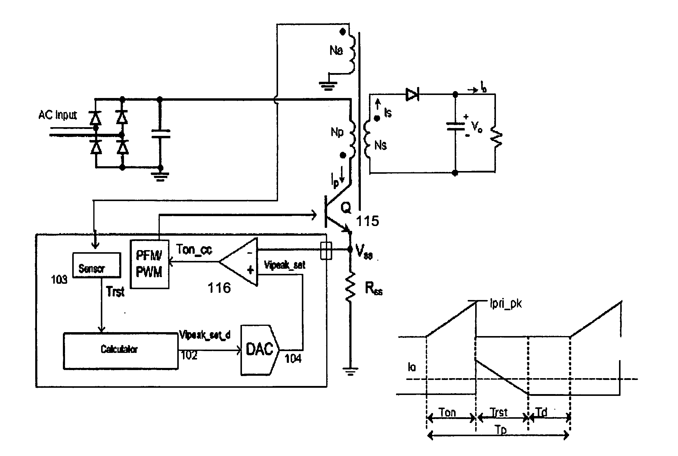
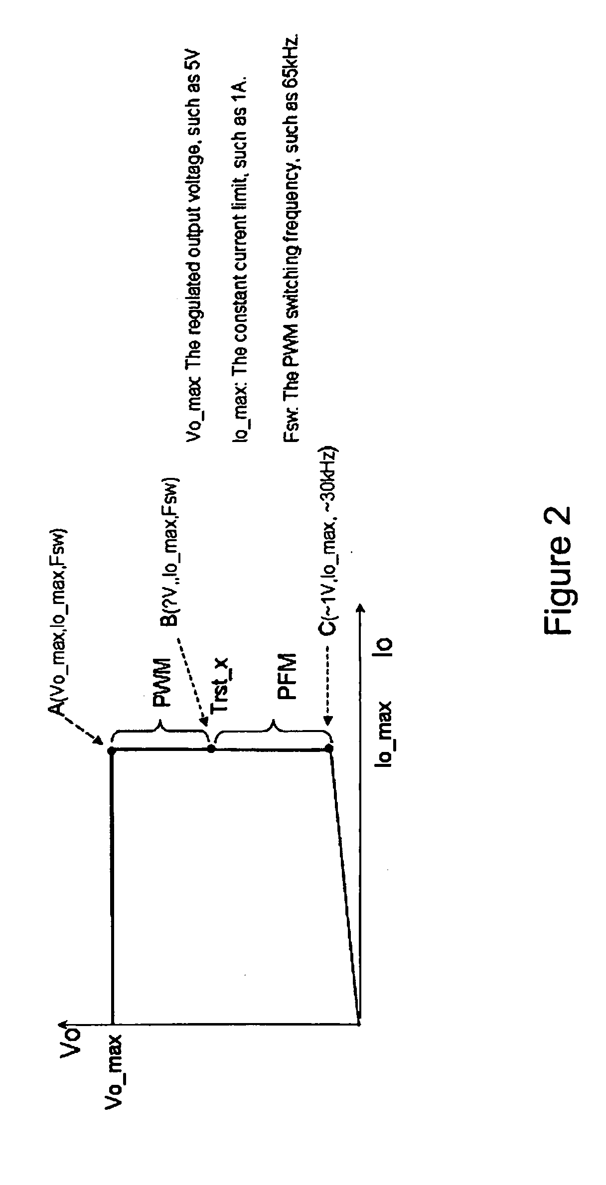
A hybrid constant current control system that uses both pulse width modulation (PWM) and pulse frequency modulation (PFM) control. When transitioning from constant voltage mode to constant current mode the present invention can continue to control using PWM. Thereafter, when the voltage has dropped, the present invention smoothly transitions to PFM mode. The point of transition is based upon the switching frequency and the lowest rated voltage of operation. The system and method avoids very short (narrow) Ton times which ensures accurate constant current (CC) control with bipolar junction transistor (BJT) devices. The present invention also avoids acoustic noise because the switching frequency is maintained at a high enough level to avoid such acoustic noise even when the energy transferred through the transformer is still substantial and the output voltage is not too low. In addition the output current limit is insensitive to variation in the inductance-input voltage ratio, and is minimized against leakage inductance.

Description

RELATED APPLICATIONS[0001]This application claims priority from U.S. provisional application No. 60 / 968,539 filed on Aug. 28, 2007 which is incorporated by reference herein in its entirety.FIELD OF THE INVENTION[0002]The invention relates generally to power supply controllers and more particularly to hybrid controllers for power supplies using both pulse width modulation (PWM) and pulse frequency modulation (PFM).BACKGROUND OF THE INVENTION[0003]Conventional power supply controllers use metal-oxide semiconductor field-effect transistor (MOSFET) transistors as switches such as, for example, U.S. Pat. No. 6,972,969, U.S. patent application Ser. No. 11 / 745,299 filed on May 7, 2007 and U.S. patent application Ser. No. 11 / 558,326 filed on Nov. 9, 2006 which are incorporated by reference herein in their entirety.[0004]However, the output current limit control techniques used in conventional systems can not be directly used when a bipolar junction transistor (BJT) switching device is used ...

Claims


Application Information

Patent Timeline
IPC IPC(8): H02M7/155
CPCH02M3/33523
Inventor LI, YONGZHENG, JUNJIEYAN, LIANGKESTERSON, JOHNWANG, XIAO YAN
Owner DIALOG SEMICONDUCTOR INC
Why Eureka
Try Eureka