DC power source apparatus

a power source and power supply technology, applied in the direction of electric variable regulation, process and machine control, instruments, etc., can solve the problems of common-mode noise and affect other devices badly, and achieve the effect of reducing common-mode nois

Inactive Publication Date: 2012-08-21
SANKEN ELECTRIC CO LTD
View PDF7 Cites 0 Cited by
  • Summary
  • Abstract
  • Description
  • Claims
  • Application Information

AI Technical Summary

Benefits of technology

[0016]To reduce the common-mode noise due to high-frequency currents, there is a related art illustrated in FIGS. 5 to 8 in which FIG. 5 is a circuit diagram illustrating a DC converter according to the related art, FIG. 6 is a sectional view illustrating a transformer arranged in the DC converter of FIG. 5, FIG. 7 is a schematic view illustrating windings of the transformer of FIG. 6, and FIG. 8 is a view illustrating parasitic capacitances among the windings of FIG. 7. This related art employs a specific winding technique for a primary winding P2.
[0023]In this way, this related art arranges the winding layers P1-1 and P2-1 that are connected to the switching element Q1 and involve large voltage changes at positions farthest from the secondary winding S to cause small parasitic capacitances with respect to the secondary winding S. Also, the related art arranges the winding layers P2-2 and P1-2 that are connected to the stable potential line Ls and involve little voltage changes at positions closest to the secondary winding S to cause large parasitic capacitances. This arrangement reduces high-frequency currents passing from the first and second primary windings P1 and P2 to the secondary winding S. The DC converter of this related art has a simple structure, reduces common-mode noise, and minimizes leakage inductance because both the first and second primary windings P1 and P2 are in contact with the secondary winding S.
[0026]The present invention provides a DC power source apparatus having a transformer that has a simple structure to minimize noise radiation without increasing leakage inductance.

Problems solved by technology

The high-frequency currents passed to the ground cause common-mode noise.
The common-mode noise leaks to the DC power source E and radiates into the air, to badly affect other devices.

Method used


Image

  • DC power source apparatus
  • DC power source apparatus
  • DC power source apparatus

Examples


Embodiment Construction

[0043]A DC power source apparatus according to an embodiment of the present invention will be explained in detail with reference to the drawings.

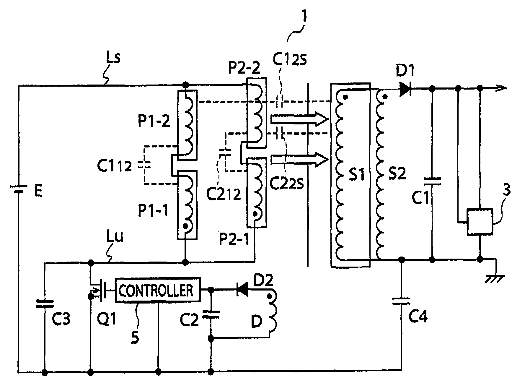
[0044]FIG. 9 is a circuit diagram illustrating a DC power source apparatus according to an embodiment of the present invention, FIG. 10 is a sectional view illustrating a transformer arranged in the DC power source apparatus of FIG. 9, FIG. 11A is a schematic view illustrating windings of a part A of FIG. 10, FIG. 11B is a schematic view illustrating windings of a part B of FIG. 10, FIG. 12A is a view illustrating parasitic capacitances among the windings of FIG. 11A, and FIG. 12B is a view illustrating parasitic capacitances among the windings of FIG. 11B.

[0045]In FIG. 9, parts corresponding to those illustrated in FIG. 5 are represented with like reference marks. In FIGS. 9 and 10, the transformer 1 has a core (iron core) 11 that is a combination of U-shaped cores and has a center gap, a bobbin 10 into which a leg 11-1 of the core 11 is i...


PUM


Abstract

A DC power source apparatus converts a DC input voltage into high-frequency power by turning on / off a switching element connected to a primary winding of a transformer and converts the high-frequency power transmitted to a secondary winding of the transformer into a DC output voltage. The primary and secondary windings of the transformer include a core winding set having a primary winding P1 wound around a leg of a core defining a closed magnetic path and a secondary winding externally wound around the primary winding and another core winding set having a primary winding P2 wound around a leg of the core and a secondary winding externally wound around the primary winding. The primary winding of each of the two core winding sets has a plurality of winding layers among which a lowermost one that is closest to the core is connected to the switching element.

Description

BACKGROUND OF THE INVENTION[0001]1. Field of the Invention[0002]The present invention relates to a DC power source apparatus, and particularly, to a power converting transformer used for a DC power source apparatus.[0003]2. Description of the Related Art[0004]FIG. 1 is a circuit diagram illustrating a DC power source apparatus according to a related art. The apparatus includes a switching element Q1 made of, for example, a MOSFET that is turned on / off to intermittently convert a DC input voltage from a DC power source E into high-frequency power, a transformer 1a having primary windings P1 and P2 between the switching element Q1 and a positive electrode of the DC power source E, to transmit the high-frequency power from the primary side to the secondary side, a rectifying-smoothing circuit consisting of a diode D1 and a smoothing capacitor C1, to convert the high-frequency power transmitted to the secondary side into a DC output voltage and supply the DC output voltage to a load, an...

Claims


Application Information

Patent Timeline
Patent Type & Authority Patents(United States)
IPC IPC(8): H02M3/22
CPCH01F30/06H02M3/33507H01F27/2823H01F27/306H01F27/38H01F41/0633H01F41/082
Inventor UTSUNO, MIZUKIWATANABE, MASAYUKISUGIURA, HIDETOTAMEGAI, ERI
Owner SANKEN ELECTRIC CO LTD
Why Eureka
Try Eureka