
Filter for adaptive noise reduction and sharpness enhancement for electronically displayed pictures

a filter and picture technology, applied in the field of image processing system, can solve the problems of reducing the quality of perceived images, requiring more hardware, and complex sophisticated methods, and achieve the effect of enhancing noise reduction

Active Publication Date: 2009-03-05
BANG & OLUFSEN
View PDF4 Cites 20 Cited by
  • Summary
  • Abstract
  • Description
  • Claims
  • Application Information

AI Technical Summary

Benefits of technology

[0007]The purpose of the filter is to filter out noise and MPEG artifacts, (i.e. blocking and ringing) from the received images and at the same time to enhance the sharpness of these images. Furthermore it is the purpose to perform this by means which do not require huge data registers and very fast computers.
[0013]The measured global noise value will control the noise reduction in such a way that for high noise values the noise reduction will be increased and for low noise values the noise reduction will be decreased. For higher noise values the sharpness enhancement will be reduced.
[0015]The local MPEG ringing artifact and MPEG block edge detection will control the noise reduction in such a way that the noise reduction will be enhanced in case of the detection of an MPEG ringing or MPEG edge.

Problems solved by technology

In particular two influences occur that reduce the quality of the perceived image: noise that introduces random stepwise variation between neighboring pixels and data reduction algorithms that introduce “ringing” and “blocking”.
The sophisticated methods are both very complex, calculation-intensive, and require more hardware than it is generally considered reasonable to include in equipment for home entertainment, such as TV and video monitors or computer screens.

Method used


Image

  • Filter for adaptive noise reduction and sharpness enhancement for electronically displayed pictures
  • Filter for adaptive noise reduction and sharpness enhancement for electronically displayed pictures
  • Filter for adaptive noise reduction and sharpness enhancement for electronically displayed pictures

Examples


Embodiment Construction

Filter Main Functional Blocks

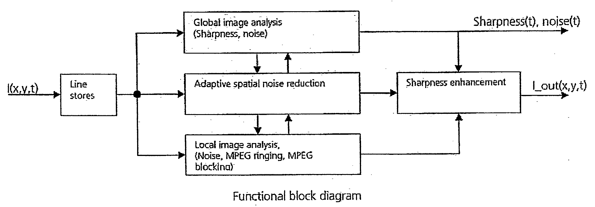
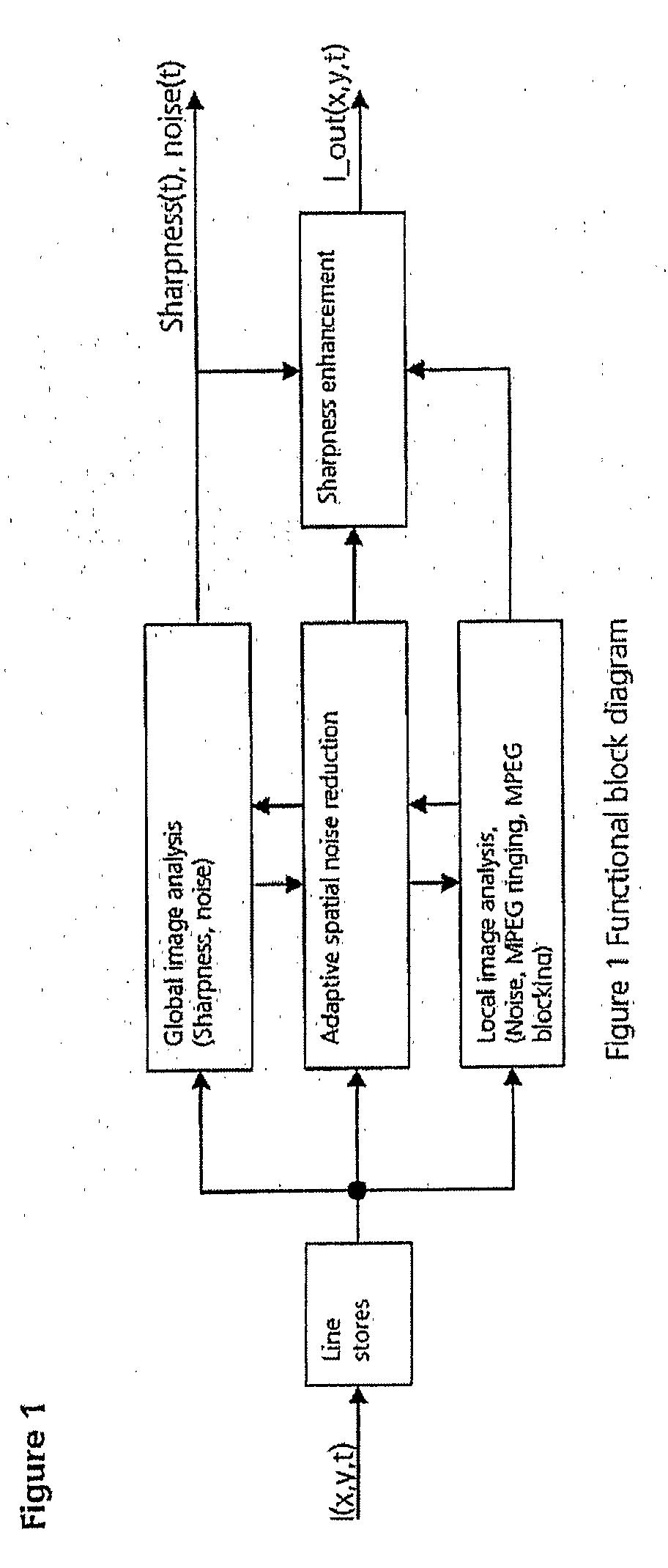
[0018]The main components of the system are outlined in FIG. 1 and constitute:

A) Global image analysis

B) Local image analysis for control of C) and D) on a pixel-by-pixel basis

C) Adaptive spatial noise reduction

D) Adaptive 2-dimensional sharpness enhancement combined with horizontal sharpness enhancement.

[0019]The filter structure is intended to work on digitized analogue TV signals as well as decoded digital TV signals in standard or high definition.

[0020]The processing is performed in an YCbCr (luminance and color) representation, and received signals in other formats may be converted accordingly.

[0021]The system operates on interlaced and progressive input formats with each component represented by 8 or 10 bit.

I(x, y, t) represents the incoming image.

x, y, t locates the image at its sample positions in the horizontal, vertical and temporal sampling dimension respectively.

I_out(x, y, t) represents the noise reduced and sharpness enhanced image

Sharpness...


PUM


Abstract

Electronic images that are degraded by noise and data reduction, such as MPEG encoding, display artifacts in the reproduced image, such as ringing (“ripples”) and blocks (“huge pixels”), and noise in the image may be apparent as graininess. By performing image analysis, both on a frame-by-frame and pixel-by-pixel basis it is possible to identify and separate edges in the image, ringing artifacts and the boundaries between block transitions. By applying noise reduction according to the analysis, followed by sharpness enhancement, it is possible to clean up the image for further utilization.

Description

BACKGROUND OF THE INVENTION[0001]1. Field of the Invention[0002]The present invention relates to methods for use in an image processing system to enhance the overall picture quality of an electronically displayed picture.[0003]2. Description of Related Art[0004]Modem storage and transmission of pictures occurs by electronic means, in which analog electronic signals are converted to digital groups of numbers representing the total information necessary to re-create one picture element (one pixel) on a screen, such as a CRT screen or a plasma screen or a Liquid Crystal Display. Electronic picture may also originate in the digital domain. A picture is defined by many parameters, some of which are related to the human visual perception. Contrasts between series of neighboring pixels are perceived as contours, and correct representation of such contours as well as gradual changes in e.g. chromaticity are important elements in a high quality picture representation. In particular two influ...

Claims


Application Information

Patent Timeline
IPC IPC(8): G06K9/40
CPCG06T5/002G06T2207/20012G06T5/40G06T5/003G06T5/73G06T5/70
Inventor PEDERSEN, JESPER MELDGAARD
Owner BANG & OLUFSEN
Learn More