Vehicle control system

a technology of vehicle control and control system, applied in the direction of process and machine control, digital computer details, instruments, etc., to achieve the effect of small valu

Active Publication Date: 2009-03-05
ADVICS CO LTD
View PDF13 Cites 57 Cited by
  • Summary
  • Abstract
  • Description
  • Claims
  • Application Information

AI Technical Summary

Benefits of technology

[0025]According to a still further feature of the invention, the acceleration setting portion sets the target acceleration at a smaller value, as the vehicle speed becomes larger.
[0026]As a result that the ta...

Problems solved by technology

In particular, an operation for automatically changing the vehicle condition to the vehicle traveling condition makes it possible to carry out fin...

Method used


Image

  • Vehicle control system
  • Vehicle control system
  • Vehicle control system

Examples


first embodiment

[0054]A vehicle control system according to a first embodiment of the present invention will be hereinafter explained with reference to the drawings.

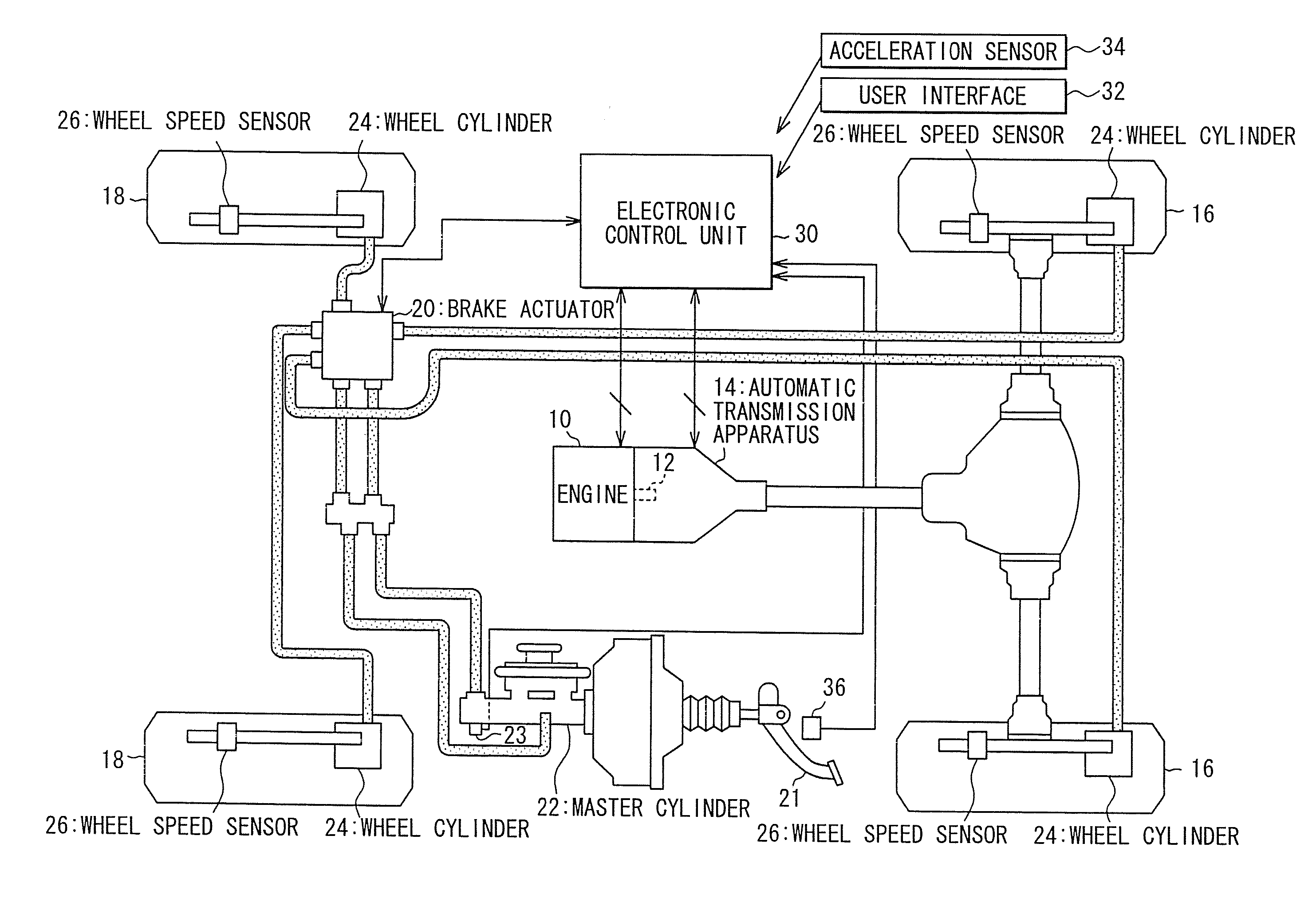
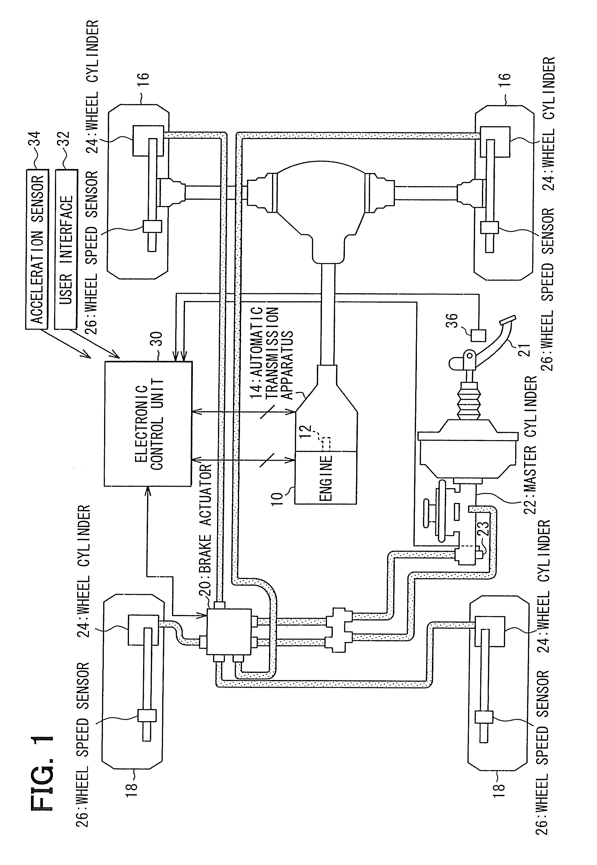
[0055]FIG. 1 shows an entire structure for the vehicle control system according to the embodiment.

[0056]An automatic transmission apparatus 14 is connected to a crank shaft 12 of an engine 10 (an internal combustion gasoline engine). A rotational force of the crank shaft 12 of the engine 10 is transmitted to driving wheels 16, wherein rotational speed is changed by the automatic transmission apparatus 14.

[0057]Braking force will be applied to the driving wheels 16 and driven wheels 18 by a hydraulic brake actuator 20. The hydraulic brake actuator 20 controls pressure of working fluid applied to respective wheel cylinders 24 for the respective wheels (the driving wheels 16 and the driven wheels 18), in order to respectively adjust the braking force. The hydraulic brake actuator 20 has a function for adjusting the braking force to be gene...

second embodiment

[0152]A second embodiment, in particular such points different from the first embodiment, will be explained with reference to the drawing.

[0153]FIG. 19 shows an estimating method for the coefficient “μ” of friction between the road surface and the vehicle wheels. According to the embodiment, the coefficient “μ” of friction is estimated based on information from a vehicle navigation system, weather information, information from probe cars, and so on. An information for an area in which the vehicle is traveling can be obtained from the navigation system. An information for the current weather can be obtained from the weather information. According to such local area information and the weather information, it is possible to get an information in a snow country that it is snowing, or there remains snow cover on the roads even through it is clear sky, and so on. In addition, the coefficient “μ” of friction can be set for the snow cover roads and the acceleration “as1” for the vehicle st...


PUM


Abstract

When a vehicle is started on an uphill road, slip may easily occur between vehicle wheels and a sloping road surface. When vehicle condition is changed from its stopping condition to its traveling condition on the uphill road, vehicle acceleration is controlled in a feed-back operation in such a manner that a target acceleration is made smaller as road gradient becomes larger or coefficient of friction becomes smaller.

Description

CROSS REFERENCE TO RELATED APPLICATION[0001]This application is based on Japanese Patent Application No. 2007-221143 filed on Aug. 28, 2007, the disclosure of which is incorporated herein by reference.FIELD OF THE INVENTION[0002]The present invention relates to a vehicle control system having a function for automatically controlling torque generated at a driving power generating apparatus when a vehicle is changed from its stopping condition to traveling condition.BACKGROUND OF THE INVENTION[0003]As a vehicle control system of this kind, it is proposed in Japanese Patent Publication No. 2005-51886, for example, that a torque to be applied by an electric motor to vehicle driving wheels is set, based on a value which is calculated by multiplying a counterbalancing torque to a force of gravitation in a vehicle backward direction by a reflection ratio, or based on a required torque corresponding to an acceleration pedal stroke operated by a vehicle driver, whichever is larger. The refle...

Claims


Application Information

Patent Timeline
IPC IPC(8): G05D13/66B60T7/12B60T8/172B60W10/04B60W10/06B60W10/18B60W10/184B60W30/00B60W30/02
CPCB60W10/06B60W10/10B60W10/184B60W30/16B60W30/18027B60W30/18118Y10T477/675B60W2520/105B60W2520/28B60W2540/12B60W2550/142B60W2720/106B60W40/076B60W2552/15
Inventor KODAMA, HIROYUKITAKEDA, MASAYOSHINAKAI, YASUHIRO
Owner ADVICS CO LTD
Why Eureka
Try Eureka