Chromatography column

a chromatography column and column body technology, applied in the field of chromatography columns, can solve the problems of inside the column, elasticity of the packing, and rapid and then slower expansion of the packed gel sedimen

Active Publication Date: 2009-03-12
REPLIGEN CORP
View PDF28 Cites 17 Cited by
  • Summary
  • Abstract
  • Description
  • Claims
  • Application Information

AI Technical Summary

Benefits of technology

[0015]After the calculated volume of a set suspension of a chromatographic medium has been loaded into the column body, the defined permanent and product-specific compression of the chromatographic medium is achieved by uniformly compressing the chromatographic medium precisely to the predetermined volume upon subsequent insertion of the plunger or sample reservoir, including the upper filter plate. The outer diameter of the plunger or sample reservoir is selected in relation to the inner diameter of the column such that after insertion into the column to a depth specified by a check ring, the plunger or sample reservoir permanently remains in this position, also in opposition to the elastic restoring forces of the compressed chromatographic media which are directed against the upper filter plate. If the dimensions of the column and its individual parts have been suitably selected, despite compression by 20%, for example, in comparison to the volume obtained from the same quantity of chromatographic material after sedimentation under gravity, the above-mentioned quasi-elastic chromatographic materials may be operated under the force of gravity after filling the sample reservoir with liquid. It is advantageously possible to initiate the longitudinal gravity-driven flow in such upright columns by short-term centrifugation of the columns without noticeable efficiency-reducing asymmetries in the flow distribution occurring in the column.
[0016]It is noted here that the columns according to the invention are preferably loaded with quasi-elastic chromatographic materials. However, nonelastic chromatographic materials may also be introduced. A defined packing is obtained even when these materials are used. Insertion of the plunger or sample chamber requires no physical compression of the chromatographic material beyond the packing density, resulting solely from sedimentation, of a packing of the same quantity of chromatographic material. When either quasi-elastic or elastic chromatographic materials are used, insertion and lowering of the plunger or sample chamber until the stop in the column body is reached causes rapid displacement of liquid from the suspension of chromatographic materials, which preferably include particles, which has just been previously loaded in the column body. The average distance between these particles is thus reduced within a few seconds in the same manner as that achieved in the prior art by the outwardly forced flow of a suitable eluent from top to bottom in the direction of the column axis.
[0017]For the chromatographic column described herein, the “classification” of the generally differently sized particles of the chromatographic material, which otherwise would occur as a result of the different sedimentation velocity of these particles, is effectively prevented. This results in an essentially homogeneous distribution of the various particle sizes in the packing of the chromatographic material, i.e., the homogeneous packing required for chromatographic applications. The production of the compressed packing thus corresponds, in a manner of speaking, to a greatly accelerated sedimentation process in which there is no time for the particles to form nonhomogeneous size distributions. Hence, larger particles cannot sediment more quickly than small particles of the same density, which otherwise would be the case. This applies for all particleized chromatographic materials which for production reasons are composed of differently sized particles, i.e., which have a particle distribution range. In contrast, for packing of monodisperse chromatographic materials the factor of accelerated compression plays no special role. In this case, however, packings which are just as homogeneous are obtained by insertion of a plunger or sample chamber. Such chromatographic materials therefore require no special treatment. The majority of applicable chromatographic materials, however, are polydisperse with respect to particle size, so that the compression described here is particularly advantageous.
[0020]The action of an external mechanical force on such a loose packing, preferably in the direction of the column axis, necessarily reduces the interspaces between the particles, with discharge of interstitial liquid, which is a condition for achieving good chromatographic separation efficiency. For greater compression, it is then increasingly possible for particles of the chromatographic material to become reversibly deformed, which may have a counterproductive effect.
[0021]It is therefore important to set the best relative compression as determined experimentally. When a force is exerted on the chromatographic material for this purpose, it has been shown that removing the force causing the compression permits a more or less rapid expansion of the compressed packing to a larger volume. In the case of ideal elasticity, the volume of a loose gravitational sediment would readjust. In practice, however, only a partial re-expansion is usually observed. Therefore, this is referred to as “pseudoelasticity” of the chromatographic material. This results in the necessity to keep compressed material in a precompressed state by use of mechanical, liquid-permeable barriers. This is easily achieved by means of the filter holders according to the invention described herein. This has proven satisfactory in particular for mini-columns, i.e., chromatographic columns having small dimensions, in particular small volumes.

Problems solved by technology

When nonelastic materials are used, after a certain period of time a defined packing of the material results inside the column due to sedimentation.
However, as soon as this pressure acting on the packed gel is discontinued, the elasticity of the packing becomes noticeable, such that an initially rapid and then slower expansion of the packed gel sediment occurs.
Such adapters generally require a complex design and contribute significantly to high manufacturing costs, in particular for small-volume columns.
For such columns, a particular difficulty of the packing procedure is closing off the column in the packed state of the chromatographic material without elastically re-expanding the gel in the process.
In contrast, simultaneous operation of multiple columns requires the use of a corresponding number of pump systems, which entails a very complex equipment setup.
Therefore, these technical solutions for simultaneous separation of multiple samples do not permit separation results of a quality known to one skilled in the art from the classical chromatographic columns.
In addition, these systems are less well suited for applications involving proteins and other high-molecular biological substances, since after a period of time air or other gas passes through the chromatographic material.
Although residual interstitial liquid may be removed from the chromatographic material by additional centrifugation, due to variable flow rates in vacuum operation in individual columns it is not possible to achieve uniform conditions for the separation processes.
A further disadvantage of vacuum-operated multicolumn systems is the potential denaturing of proteins resulting from the formation of foam when the sample exits the chromatographic material, since the partial vacuum is particularly strong at this location.
However, in this case as well the chromatographic media are present only in a low packing density as a result of sedimentation of the gel particles under the flow rate induced by gravity.
Thus, the efficiency of the separation media used, primarily with respect to the achievable plate number, is not fully utilized.
A further disadvantage of the batch method is the residual liquid in the intraporous volume of the separation medium in each step of the separation from supernatant, regardless of which method (decantation, filtration, etc.) is used for the separation.
Use of this method is therefore limited by obvious practical considerations.
From the standpoint of chromatographic separation efficiency, the technical solutions discussed have the disadvantage either that they may be parallelized only with a high expenditure of time and complexity of equipment, or that the chromatographic separation efficiency of the separation media cannot be fully utilized in the absence of sufficient and permanent compression of the media.

Method used


Image

  • Chromatography column
  • Chromatography column
  • Chromatography column

Examples


example 1

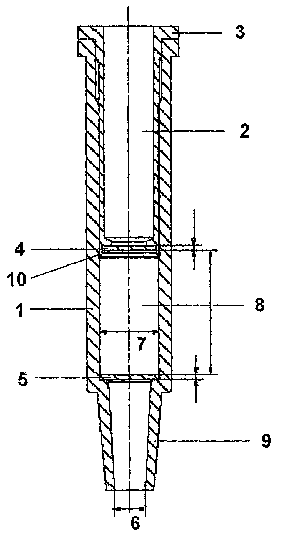
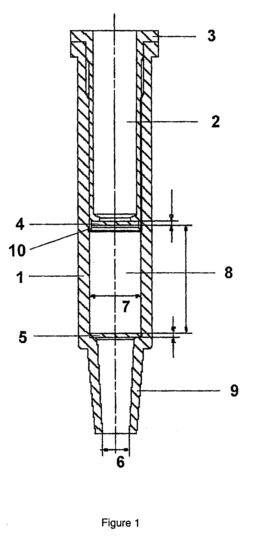
[0039]A total of 96 chromatographic columns according to the invention in the preferred embodiment according to FIG. 1, having a gel chamber inner diameter of 5 mm and a distance of 11 mm between the upper and lower filter plates, corresponding to a volume of the packed chromatographic material of approximately 216 / μL, and a total length of 38 mm were fitted with circular cutout filter plates by Freudenberg, model FO2472. The thickness of the PP / PE filter plates was approximately 0.45 mm, and the average pore size was approximately 17 μm. The upper filter integrated into the lower end of the sample chamber had a diameter of 4.6 mm, and the lower filter had a diameter of 5 mm. The filter plates were introduced into the separately provided column body and sample reservoir by use of a small insertion plunger of matching diameter. The column bodies were then placed symmetrically in rows of eight on two matching column holding plates having the dimensions of 96-well microtiter plates. T...


PUM

PropertyMeasurementUnit
diameteraaaaaaaaaa
widthaaaaaaaaaa
inner diameteraaaaaaaaaa

Abstract

Disclosed is a chromatographic column for use with chromatographic materials packed in a defined manner.Said chromatographic column is characterized in that the chromatographic material in a defined compressed state is enclosed in a column body (1), which is preferably cylindrical and is provided with a discharge opening (9), between two filter plates which are fixed at a specified distance from one another by contact with support surfaces situated inside the column body.

Description

TECHNICAL FIELD [0001]A miniature chromatographic column is disclosed in which a permanently defined compression of a chromatographic material enclosed between two filter plates is achieved by means of a plunger inserted into the column which fixes the upper filter plate in place, and which is provided with an opening of a suitable size with respect to the filter plate. By means of a multiple holding device large numbers of the columns may be used for simultaneous processing of an equivalent number of chemical or biological samples, or in applications involving stepwise elution. The flow in the columns is created by either gravitational force or centrifugal force, or a combination of both.PRIOR ART (BACKGROUND OF THE INVENTION)[0002]Chromatographic separations of chemical or biological substance mixtures in liquid samples on chromatographic materials are usually carried out using columns in which the compressed packing of these materials is fixed by an adapter which may be stationar...

Claims


Application Information

Patent Timeline
Patent Type & Authority Applications(United States)
IPC IPC(8): G01N30/60
CPCG01N30/603
Inventor VETTER, UDO JOHANNESFRIEDLE, JURGENSTRITTMATTER, MANFREDBRITSCH, LOTHAR
Owner REPLIGEN CORP
Why Eureka
Try Eureka