Micromagnetic Device and Method of Forming the Same

Active Publication Date: 2009-03-12
INTEL CORP
View PDF99 Cites 38 Cited by
  • Summary
  • Abstract
  • Description
  • Claims
  • Application Information

AI Technical Summary

Benefits of technology

[0009]These and other problems are generally solved or circumvented, and technical advantages are generally achieved, by advantageous embodiments of a micromagnetic device including a substrate, and a magnetic core layer formed over the substrate from a magnetic alloy. The ma

Problems solved by technology

Thus, although substantial progress has been made in development of techniques for production of a highly integrated power converter that is formed on a single chip, these processes are not sui

Method used


Image

  • Micromagnetic Device and Method of Forming the Same
  • Micromagnetic Device and Method of Forming the Same
  • Micromagnetic Device and Method of Forming the Same

Examples


Embodiment Construction

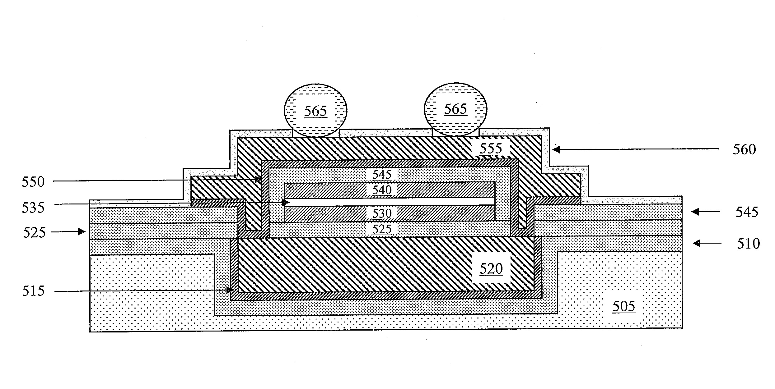
[0023]The making and using of embodiments are discussed in detail below. It should be appreciated, however, that the invention provides many applicable inventive concepts that can be embodied in a wide variety of specific contexts. The specific embodiments discussed are merely illustrative of specific ways to make and use the invention, and do not limit the scope of the invention.

[0024]The invention will be described with respect to exemplary embodiments in a specific context, namely, a micromagnetic device, method of forming the same and a power converter employing the same. Additionally, an electroplating tool and electrolyte employable for constructing a magnetic core layer of the micromagnetic device will also be described herein. Also, a method of processing a substrate and micromagnetic device to relieve stress induced by a conductive film will be described herein.

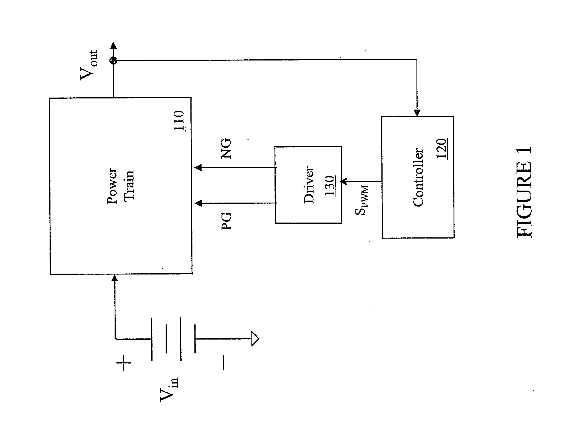
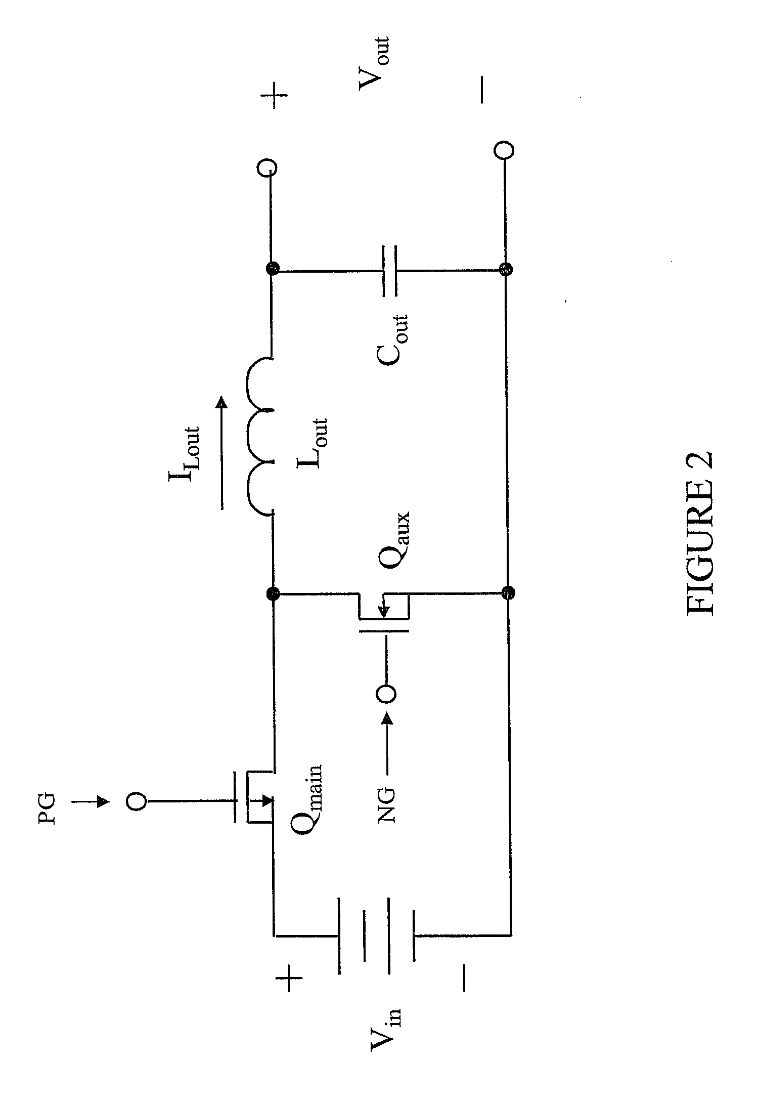
[0025]Referring initially to FIG. 1, illustrated is a block diagram of an embodiment of a power converter includin...


PUM


Abstract

A micromagnetic device including a substrate, and a magnetic core layer formed over the substrate from a magnetic alloy. The magnetic alloy includes iron, cobalt and phosphorous. A content of the cobalt is in a range of 1.8 to 4.5 atomic percent. A content of the phosphorus is in a range of 20.1 to 30 atomic percent. A content of the iron is substantially a remaining proportion of the magnetic alloy.

Description

TECHNICAL FIELD[0001]The invention is directed, in general, to magnetic devices and, more specifically, to a micromagnetic device, method of forming and power converter employing the same, and an electroplating tool and electrolyte employable for constructing a magnetic core layer of the micromagnetic device, and a method of processing a substrate and micromagnetic device.BACKGROUND[0002]A switch mode power converter (also referred to as a “power converter”) is a power supply or power processing circuit that converts an input voltage waveform into a specified output voltage waveform, which is typically a well-regulated voltage in electronic device applications. Power converters are frequently employed to power loads having tight voltage regulation characteristics such as a microprocessor with, for instance, a bias voltage of one volt or less provided by the power converter. To provide the voltage conversion and regulation functions, power converters include a reactive circuit elemen...

Claims


Application Information

Patent Timeline
IPC IPC(8): H01F27/24
CPCH01F10/132H01F17/0033H01F10/138H01F10/265H01F41/046
Inventor LOTFI, ASHRAF W.LIAKOPOULOS, TRIFON M.FILAS, ROBERT W.
Owner INTEL CORP
Why Eureka
Try Eureka