In-vivo examination apparatus

a microscope and apparatus technology, applied in the field of in-vivo examination apparatuses, can solve the problems of not being able to obtain sufficient information for observation, not being able to carry out observation with the microscope photography apparatus, and being difficult to observe, etc., to achieve the effect of not causing blurring of images

Inactive Publication Date: 2009-03-12
OLYMPUS CORP
View PDF2 Cites 23 Cited by
  • Summary
  • Abstract
  • Description
  • Claims
  • Application Information

AI Technical Summary

Benefits of technology

[0025]The observation head can be easily fixed to the living organism with the fixing means. In addition, by fixing it more reliably, even if the living organism moves significantly, it is possible to maintain the relative positional relationship between the living organism and the observation head, and it is thus possible to perform examination without causing blurring of the images.
[0026]According to the present invention, because the observation head is separated from the optical unit or the scanning unit and the observation head is fixed to the living organism, even if the living organism moves, it is possible to perform examination while maintaining a fixed relative positional relationship between the living organism and the observation head. Furthermore, by coupling the observation head and either the optical unit or the scanning unit with collimated light, there is no change to the image-forming relationship even if the relative distance between them changes. Therefore, an advantage is afforded in that it is possible to perform clear and continuous observation of the conditions inside the living organism, even if the living organism exhibits dynamic motion.
[0027]The present invention affords an advantage in that, because the optical unit and the observation head, or the observation head and the scanning unit, are connected with the optical fiber bundle, it is possible to perform clear and continuous observation of the conditions inside the living organism while allowing normal activity of the living organism.

Problems solved by technology

However, although conventional microscope photography apparatuses such as this take photographs adapted to the dynamic behavior of the specimen, because they selectively acquire images of the dynamic behavior of the specimen in a stationary, in-focus state while keeping the focal length of the camera constant, they suffer from problems such as choppiness of the acquired images, missing portions of the observed images, and discontinuous and jerky motion, thus making observation difficult.
In particular, when the amount of motion of the specimen in the direction of the optical axis of the camera is large, the stationary, in-focus state is limited to only an instant of the entire motion; hence, the method in Patent Document 1 for selectively acquiring images in a stationary, in-focus state suffers from the problem that it is not possible to obtain sufficient information required for observation.
In such a case, because the specimen moves significantly, there is a problem in that it is not possible to carry out observation with the microscope photography apparatus of Patent Document 1.

Method used


Image

  • In-vivo examination apparatus
  • In-vivo examination apparatus
  • In-vivo examination apparatus

Examples


first embodiment

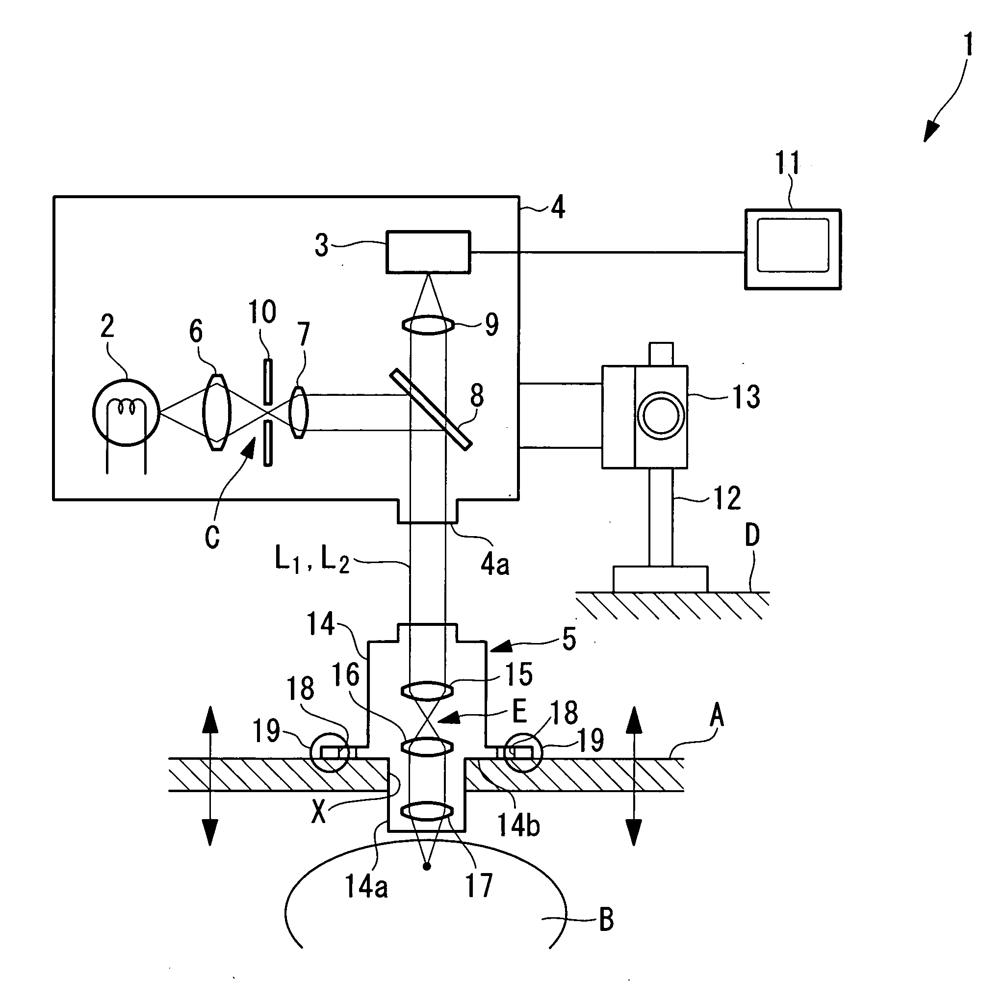
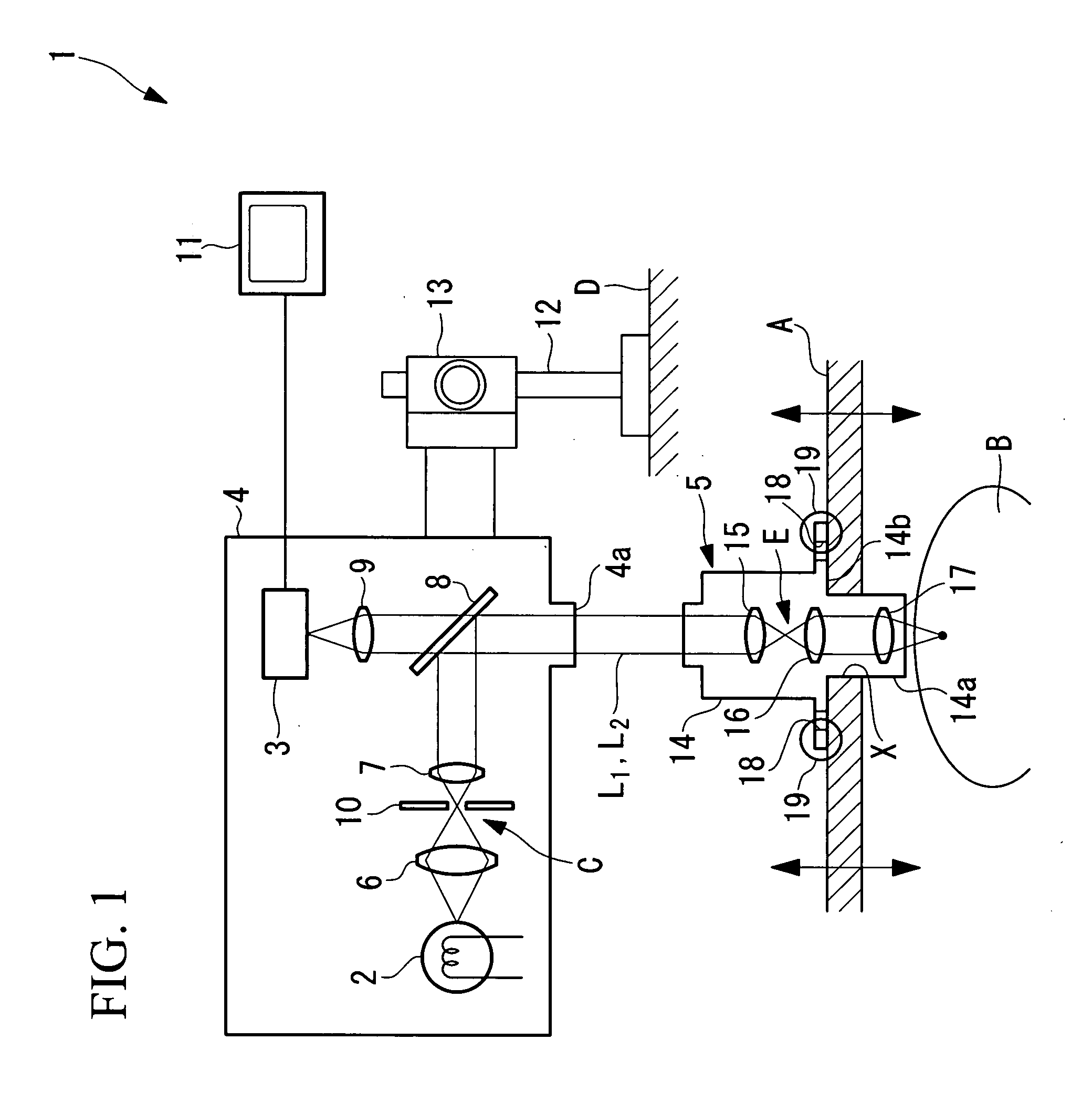
[0033]An in-vivo examination apparatus 1 according to the present invention will be described below with reference to FIG. 1.

[0034]As shown in FIG. 1, the in-vivo examination apparatus 1 according to this embodiment includes an optical unit 4 provided with a light source 2 for emitting illumination light and an image-acquisition device (for example, a charged coupled device: CCD) 3; and an observation head 5, which is secured to a living organism A such as a laboratory animal, for receiving light emitted from the optical unit 4 and illuminating an observation target site B in the living organism A, as well as for emitting return light from the living organism A towards the optical unit 4.

[0035]The optical unit 4 includes a focusing lens 6 for focusing light from the light source 2 to form an intermediate image C, a collimator lens (first collimator optical system) 7 for collecting light forming the intermediate image C and collimating it, a half mirror 8, and a focusing lens 9 for f...

second embodiment

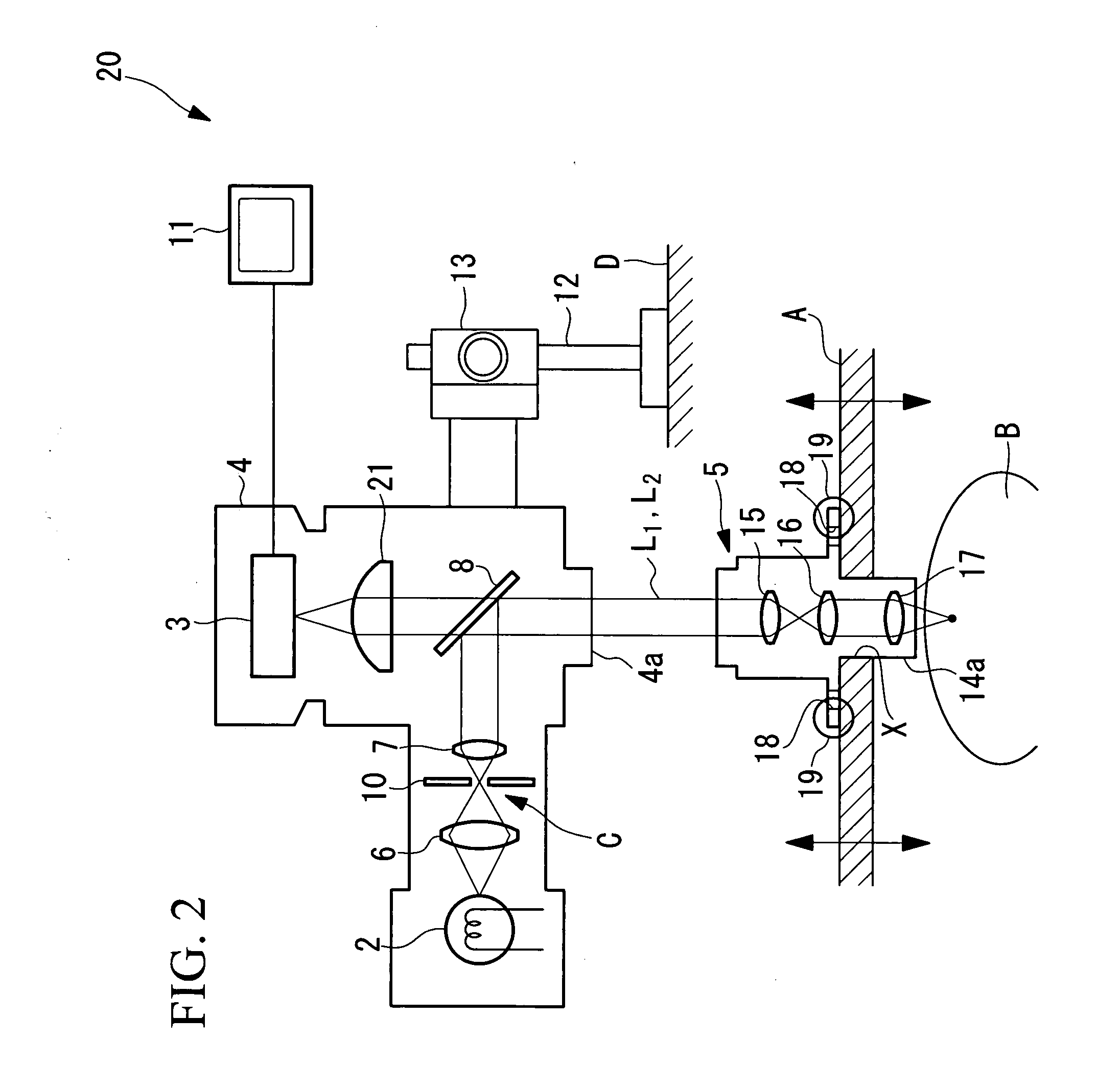
[0048]Next, an in-vivo examination apparatus 20 according to the present invention will be described with reference to FIG. 2.

[0049]In the description of this embodiment, parts having the same configuration as those in the in-vivo examination apparatus 1 according to the first embodiment described above are assigned the same reference numerals, and a description thereof is omitted.

[0050]As shown in FIG. 2, the in-vivo examination apparatus 20 according to this embodiment differs from the in-vivo examination apparatus 1 of the first embodiment in that, the image-forming lens for imaging the return light on the image-acquisition device 3 is formed of an fθ lens 21.

[0051]According to this embodiment, when the collimated light L2 returning from the observation head 5 is introduced into the optical unit 4 via the opening 4a, it is transmitted through the half-mirror 8 and is imaged by the fθ lens 21. Accordingly, an image of the examination target site B is acquired by the image-acquisit...

third embodiment

[0054]Next, an in-vivo examination apparatus 30 according to the present invention will be described below with reference to FIG. 3.

[0055]In the description of this embodiment, parts having the same configuration as those in the in-vivo examination apparatus 1 according to the first embodiment described above are assigned the same reference numerals, and a description thereof is omitted.

[0056]As shown in FIG. 3, the in-vivo examination apparatus 30 according to this embodiment includes an optical unit 33 including a laser light source 31 and a light detector 32; an optical fiber 34 for transmitting laser light from the laser light source 31 and fluorescence to the light detector 32; a scanning unit 35 for two-dimensionally scanning the laser light transmitted by the optical fiber 34; and an observation head 5 which is fixed to a living organism A, such as a laboratory animal.

[0057]A collimator lens 36, a dichroic mirror 37, and focusing lenses 38 and 39 are provided in the scanning ...


PUM


Abstract

When carrying out in vivo examination of a living organism, the behavior in the interior thereof is continuously observed with clear images. Provided is an in-vivo examination apparatus 1 comprising an optical unit 4 including a light source 2 and an image acquisition device 3; and an observation head 5, which is disposed with a gap with respect to the optical unit 4 and which is fixed to a living organism A, wherein the optical unit 4 includes a first collimator optical system 7 for converting light from the light source 2 into collimated light L1 and introducing it into the observation head 5 and an image-forming optical system 9 for focusing return light from the observation head 5 to form an image at the image-acquisition device 3, and wherein the observation optical head 5 includes a second collimator optical system 15 for focusing the collimated light L1 incident from the optical unit 4 to irradiate an examination target site B in the living organism A, as well as for converting return light from the living organism into collimated light L2 and introducing it into the optical unit 4.

Description

TECHNICAL FIELD[0001]The present invention relates to in-vivo examination apparatuses for examining organisms while they are still alive (in vivo).BACKGROUND ART[0002]Recently, visualization of ion concentration, membrane potential an so forth has been performed with fluorescence probes using optical microscopes; as specimens, for example, observation of the biological function of nerve cells and so forth, particularly the observation of dynamic behavior, has been carried out.[0003]A known apparatus for observing such dynamic behavior is a microscope photography apparatus (for example, see Patent Document 1).[0004]Patent Document 1: Japanese Unexamined Patent Application, Publication No. 2000-275539.DISCLOSURE OF INVENTION[0005]However, although conventional microscope photography apparatuses such as this take photographs adapted to the dynamic behavior of the specimen, because they selectively acquire images of the dynamic behavior of the specimen in a stationary, in-focus state wh...

Claims


Application Information

Patent Timeline
Patent Type & Authority Applications(United States)
IPC IPC(8): G02B21/36
CPCG02B21/0028G02B21/362G02B21/361G02B21/082
Inventor TANIKAWA, YOSHIHISAKAWANO, YOSHIHIRO
Owner OLYMPUS CORP
Why Eureka
Try Eureka