

Silicified electrolyte material for fuel cell, method for its preparation and fuel cell using same
a technology of fuel cell and electrolyte, which is applied in the direction of fuel cell, chemical vapor deposition coating, sustainable buildings, etc., can solve the problems of limiting the capacity of such an electrolyte to absorb water and increase the crosslinking rate, and achieves high proton conductivity and high deposition rate
- Summary
- Abstract
- Description
- Claims
- Application Information
AI Technical Summary
Benefits of technology
Problems solved by technology
Method used
Image

Examples
Embodiment Construction
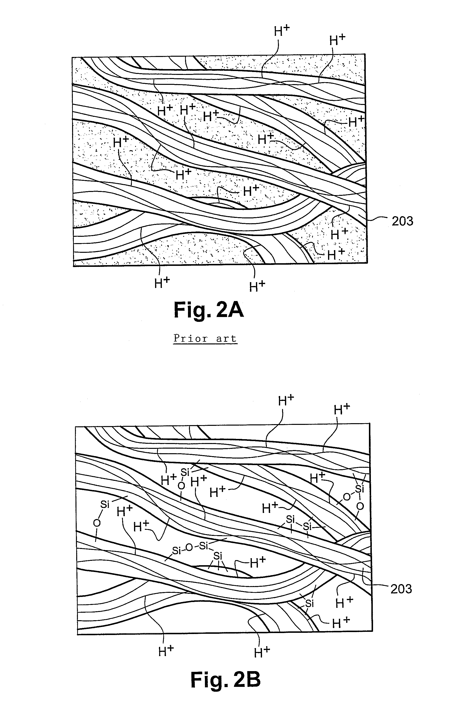
[0063]FIG. 2B illustrates, at the scale of 3 μm, the structure of the material of the present invention. According to the invention, this material has a matrix 203 comprising carbon (C), fluorine (F), oxygen (O) and hydrogen (H). As stated previously, this matrix forms the framework of an electrolytic membrane and it is therefore also called a skeleton.
[0064]As shown in FIG. 2B, this matrix further comprises silicon (Si), present in the form of bridges formed by silicon-silicon (—Si—Si—), silicon-oxygen-silicon (—Si—O—Si—) and / or silicon-oxygen-carbon (—Si—O—C—), and / or silicon-carbon (—Si—C—) groups. These bridges, by definition, form bonds in the matrix and particularly between the various fibers, shown in FIG. 2B, constituting this matrix.
[0065]In the example in FIG. 2B, the silicon atoms account for 1% of the sum of the number of carbon and fluorine atoms present in the matrix 203. Thus, the ratio of the atomic percentage of silicon present in the matrix 203 to the sum of the at...
PUM
| Property | Measurement | Unit |
|---|---|---|
| flow rate | aaaaa | aaaaa |
| flow rate | aaaaa | aaaaa |
| power | aaaaa | aaaaa |
Abstract
Description
Claims
Application Information