
Method for forming pattern of semiconductor device

a technology of semiconductor devices and patterns, applied in the direction of semiconductor/solid-state device manufacturing, basic electric elements, electric devices, etc., can solve the problems of difficult to form fine patterns having a cd less than the short wavelength, difficult to form fine patterns, and uneven cd of patterns, so as to improve yield and reliability of devices

Inactive Publication Date: 2009-03-19
SK HYNIX INC
View PDF8 Cites 133 Cited by
  • Summary
  • Abstract
  • Description
  • Claims
  • Application Information

AI Technical Summary

Benefits of technology

[0018]Various embodiments of the present invention relate to a method for forming a pattern of a semiconductor device that comprises forming a line / space pattern over a semiconductor substrate; forming a spacer on the sidewalls of the line pattern; using the spacer as a hard mask pattern that defines a fine pattern and thereby improving yield and reliability of the device.

Problems solved by technology

As a result, it is difficult to form a fine pattern having a CD of less than the short wavelength.
When the alignment process for creating the second photoresist pattern 85b is not performed accurately, a CD of the pattern will not be uniform.
As mentioned above, in the conventional method, it is difficult to form a fine pattern due to a resolution limit of an exposer.
When an exposure process is performed twice in the double patterning process to overcome the limit, patterns may be misaligned to degrade yield and reliability of the semiconductor device.

Method used


Image

  • Method for forming pattern of semiconductor device
  • Method for forming pattern of semiconductor device
  • Method for forming pattern of semiconductor device

Examples


Embodiment Construction

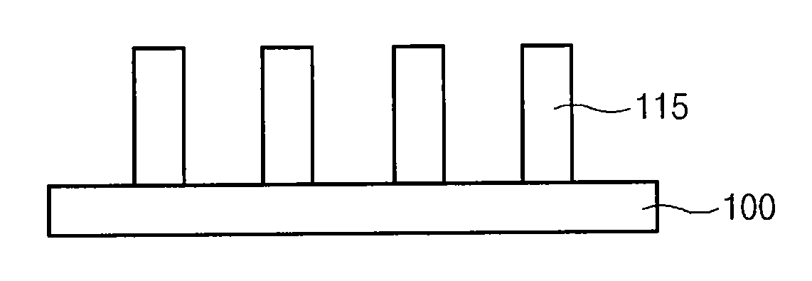
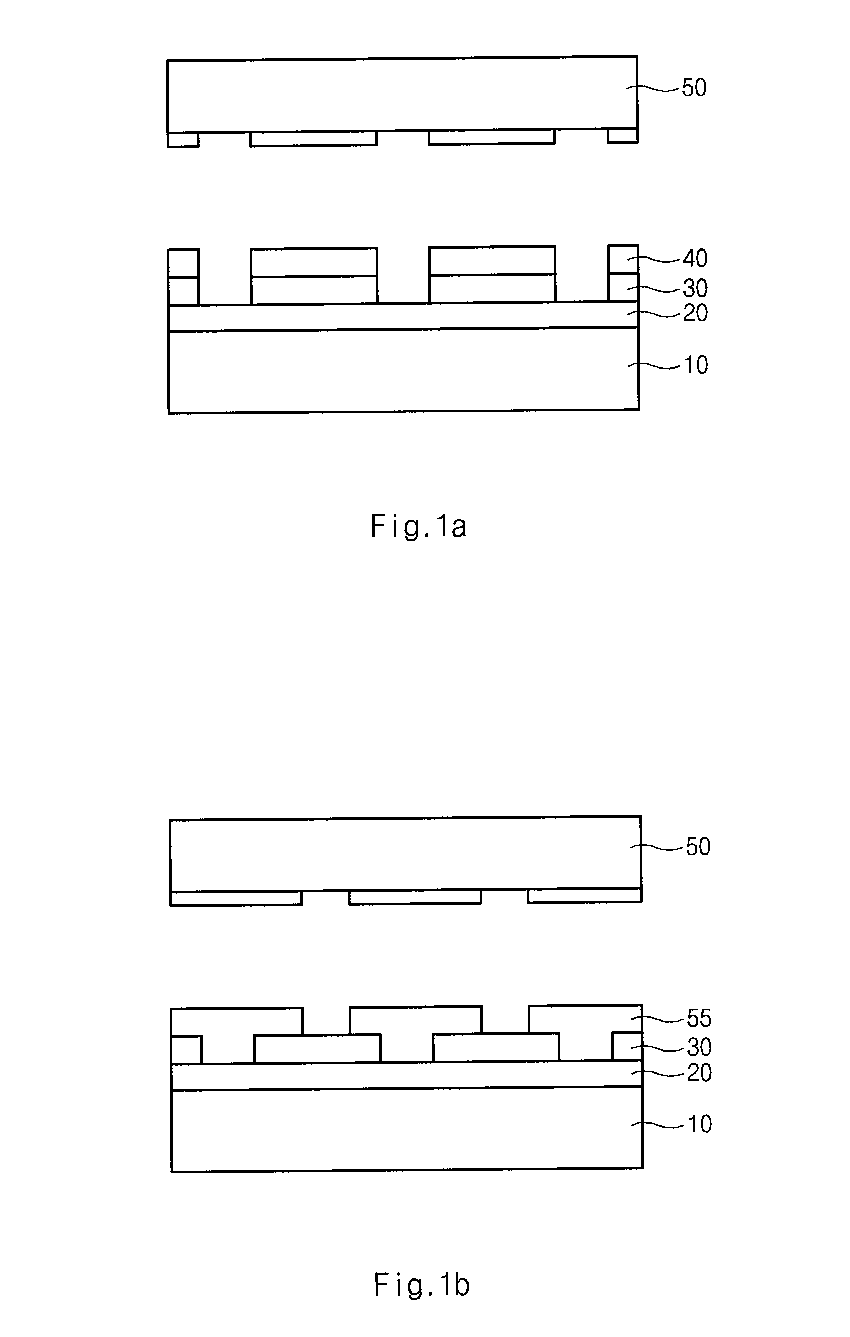
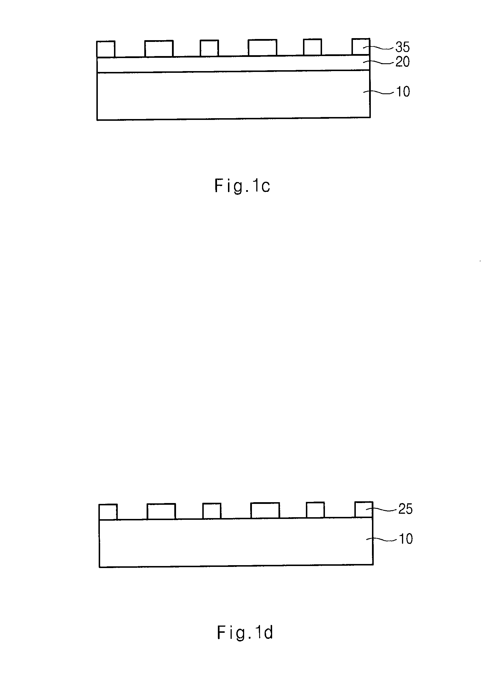
[0028]FIGS. 3a to 3d are cross-sectional diagrams illustrating a method for forming a fine pattern of a semiconductor device according to an embodiment of the present invention. In FIG. 3a, a first polysilicon layer 110 is formed over a semiconductor substrate 100. The first polysilicon layer 110 is used as a hard mask. Although not shown an underlying layer such as a gate material layer may be disposed between the first polysilicon layer 110 and the semiconductor substrate 100.

[0029]An etch barrier film 120 and a sacrificial oxide film 130 is formed over the first polysilicon layer 110. The etch barrier film 120 includes a nitride film and the sacrificial oxide film 130 includes a PE-TEOS film.

[0030]A second polysilicon layer 140 is formed over the sacrificial oxide film 130, and a first photoresist pattern 150 is formed which defines a line pattern. The first photoresist film 150 has a thickness ranging from about 800 Å to about 1200 Å. A critical dimension ratio of line width to ...


PUM


Abstract

A method for forming a fine pattern of a semiconductor device comprises: forming a first hard mask film and an etch barrier film over a semiconductor substrate; forming a sacrificial pattern over the etch barrier film; forming a spacer on sidewalls of the sacrificial pattern; removing the sacrificial pattern; etching the etch barrier film and the hard mask film with the spacer as an etch mask to form an etch barrier pattern and a hard mask pattern; and removing the spacer and the etch barrier pattern, thereby improving yield and reliability of the device.

Description

CROSS-REFERENCE TO RELATED APPLICATION[0001]Priority to Korean patent application number 10-2007-0094837, filed on Sep. 18, 2007, which is incorporated by reference in its entirety, is claimed.BACKGROUND OF THE INVENTION[0002]The present invention relates to a method for forming a pattern of a semiconductor device that comprises forming a line / space pattern over a semiconductor substrate that defines a fine pattern which improves yield and reliability of the device.[0003]As semiconductor devices become smaller and highly integrated, a chip area is increased in proportion to an increase in memory capacity. However, a cell area of the semiconductor device, which contains patterns, is reduced.[0004]In order to secure a desired memory capacity, more patterns are formed in a limited cell area, so that a critical dimension of the pattern is reduced. As a result, a lithography process is required to advance to form more finer patterns.[0005]In the lithography process, a photoresist is form...

Claims


Application Information

Patent Timeline
Patent Type & Authority Applications(United States)
IPC IPC(8): H01L21/308
CPCH01L21/0337H01L21/32139H01L21/28132H01L21/31144
Inventor BAN, KEUN DOSUN, JUN HYEUB
Owner SK HYNIX INC
Learn More