Thin Inverted Metamorphic Multijunction Solar Cells with Rigid Support
a solar cell and rigid support technology, applied in the field of solar cell semiconductor devices, can solve the problems that the demand for solar cells to meet the needs of more sophisticated applications has not kept pace with demand, and achieve the effect of improving the multi-functional solar cell
- Summary
- Abstract
- Description
- Claims
- Application Information
AI Technical Summary
Benefits of technology
Problems solved by technology
Method used
Image
Examples
second embodiment
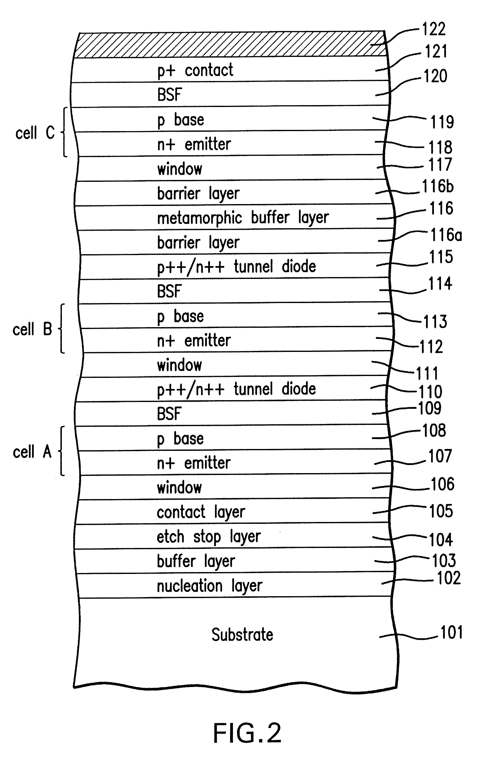
[0084]FIG. 14B is a cross-sectional view of the solar cell of FIG. 14A after the next process step in which a coverglass is added to the present invention. An adhesive is applied over the ARC layer 130 and a coverglass attached to the adhesive. Such an embodiment of a thin solar cell mounted on a thinned substrate with a coverglass is typically used for solar cells intended for space applications, or other harsh environments. Contact may be made either to layer 122, or in another variant, the adhesive 123 and surrogate substrate 124a are conductive, so the bottom metal contact 122 is electrically coupled to the substrate 124a which serves as the electrical contact to the solar cell.
[0085]FIG. 15 depicts the coupling of two adjacent solar cells Cell 1 and Cell 2 utilizing the metal layer 122 as a contact pad. The channel 510 in Cell 1 exposes a portion of the metal contact layer 122. A wire 512 is then welded or wire bonded between layer 122 on Cell 1 and the electrical contact pad ...
third embodiment
[0086]FIG. 16A is a cross-sectional view of the solar cell of FIG. 13 after the next process step according to the present invention in which an adhesive is applied over the ARC layer 130 and a coverglass attached thereto.
[0087]FIG. 16B is a cross-sectional view of the solar cell of FIG. 14A after the next process step according to the third embodiment of the present invention in which the surrogate substrate 124 is entirely removed by grinding, lapping, or etching, resulting in the finished device structure of a thin metamorphic solar cell mounted on a rigid coverglass.
[0088]It will be understood that each of the elements described above, or two or more together, also may find a useful application in other types of constructions differing from the types of constructions differing from the types described above.
[0089]Although the preferred embodiment of the present invention utilizes a vertical stack of subcells with top and bottom electrical contacts, the subcells may alternatively...
PUM
 Abstract
Description
Claims
Application Information
 - R&D
- Intellectual Property
- Life Sciences
- Materials
- Tech Scout
- Unparalleled Data Quality
- Higher Quality Content
- 60% Fewer Hallucinations
Browse by: Latest US Patents, China's latest patents, Technical Efficacy Thesaurus, Application Domain, Technology Topic, Popular Technical Reports.
© 2025 PatSnap. All rights reserved.Legal|Privacy policy|Modern Slavery Act Transparency Statement|Sitemap|About US| Contact US: help@patsnap.com


